Volume I, Section 3
3 ANTHROPOMETRY AND BIOMECHANICS
{A} For a description of the notations, see Acceleration
Regimes.
This section contains the following topics:
3.1 Introduction
3.2 General Anthropometrics
& Biomechanics Related Design Considerations
3.3 Anthropometric and
Biomechanics Related Design Data
See the video
clips associated with this section.
3.1 INTRODUCTION
{A}
3.1.1 Scope
{A}
This section presents information about human body size,
posture, movement, surface area, volume, and mass.
(Refer to Paragraph 4.9,
Strength, for information in human strength).
For purposes of this document, body dimensions and mobility
descriptions are limited to the range of personnel considered
most likely to be space module crewmembers and visiting
personnel. It is assumed that these personnel will be in
good health, fully adult in physical development, and an
average age of 40 years. A wide range of ethnic and racial
backgrounds may b represented, and crewmembers may be either
male or female. The dimensional data in
Paragraph 3.3.1, Body Size, are estimates of the size
of crewmembers in the year 2000.
Data included in this document have been primarily measured
on the ground (1-G environment). Where possible, guidelines
are provided for relating these data to space flight acceleration
regimes (from hypergravity to microgravity).
The scope of this section is focused and limited to basic
descriptive data, rather than workspace design requirements.
(Refer to Section 8.0, Architecture,
Section 9.0, Workstations,
and Section 10.0, Activity Centers
for specific crew station design considerations and requirements).
3.1.2 Terminology
{A}
The disciplines of anthropometry and biomechanics have
a specialized vocabulary of terms with specific meanings
for designating points and distances of measurement, range,
direction of motion, and mass. General anthropometric terminology
is defined in Appendix
B of Volume 2. Anatomical and anthropometric planes
and landmarks are illustrated in  Figures
3.1.2-1, 3.1.2-2, 3.1.2-3,
and 3.1.2-4 Body segments
and the planes defining these segments are defined in
Figure 3.1.2-5.
Figure
3.1.2-1 Body Planes and Orientations
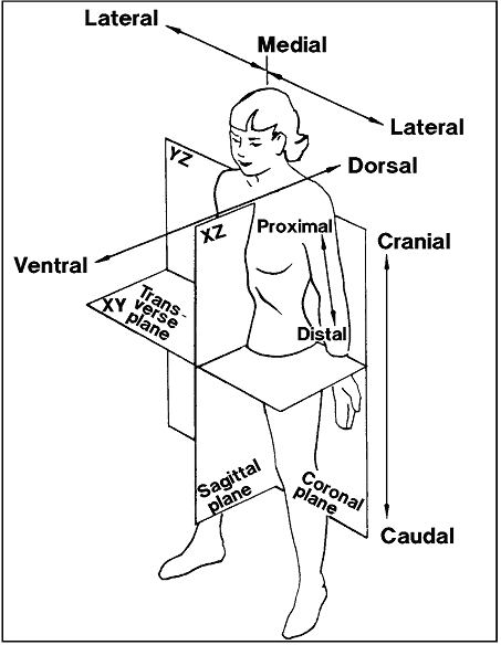
Reference: 16,
pp. III-78; NASA-STD-3000 260 (Rev A)
Figure
3.1.2-2 Anatomical and Anthropometric Landmarks
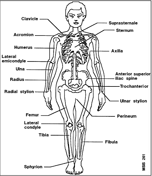
Reference: 16,
pp. III-79; NASA-STD-3000 261 (Rev A)
Figure
3.1.2-3 Anatomical and Anthropometric Landmarks
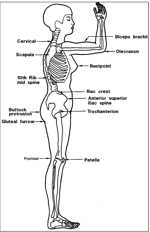
Reference: 16,
pp. III-79; NASA-STD-3000 262 (Rev A)
Figure
3.1.2-4 Anthropometric Landmarks of the Head and Face
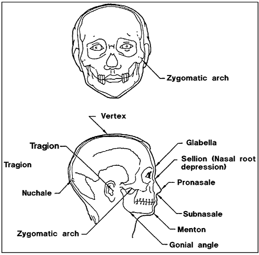
Reference: 16,
p. III-81; NASA-STD-3000 263
Figure
3.1.2-5 Illustrative view of Body Segments and Planes
of Segmentation
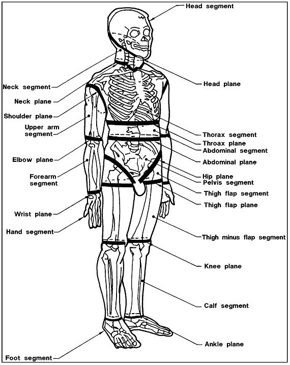
Plane Definitions
Head plane: A simple
plane that passes through the right and left gonion
points and nuchal.
Neck plane: A compound
plane in which a horizontal plane originates at cervical
and passes anteriorly to intersect with the second
plane. The second plane originates at the lower of
the two clavicle landmarks and passes superiorly at
a45 degree angle to intersect the horizontal plane.
Thorax plane: A simple
transverse plane that originates at the 10th rib midspine
landmark and passes horizontally through the torso.
Abdominal plane: A
simple transverse plane originating at the higher
of the two illica crest landmarks and continuing horizontally
through the torso.
Hip plane: A simple
plane originating midsagittaly on the perineal surface
and passing superiorly and laterally midway between
the anterior superior iliac spine and trochanterion
landmarks, paralleling the right and left inguinal
ligaments.
Thigh flap plane:
A simple plane originating at the gluteal furrow landmark
and passing horizontally through the thigh.
Knee plane: A simple
plane originating at the lateral femoral epicondyle
and passing horizontally through the knee.
Ankle plane: A simple
plane originating at the sphyrion landmark and passing
horizontally through the ankle.
Shoulder plane: A
simple plane originating at the acromion landmark
and passing inferiorly and medially through the anterior
and posterior scye point marks at the axillary level.
Elbow plane: A simple
plane originating at the olecranon landmark and passing
through the medial and lateral humeral epicondyle
landmarks.
Wrist plane: A simple
plane originating at the ulnar and radial styloid
landmarks and passing through the wrist perpendicular
to the long axis of the forearm. |
Reference: 273,
p. 9-15; NASA-STD-3000 264
3.2
GENERAL ANTHROPOMETRICS & BIOMECHANICS RELATED DESIGN
CONSIDERATIONS
{A}
3.2.1 Anthropometric
Database Design Considerations
{A}
The following are considerations that must be made when
using and applying anthropometric data.
a. Percentile Range - Design and sizing of space modules
should ensure accommodation, compatibility, operability,
and maintainability by the user population. Generally, design
limits are based on a range of the user population from
the 5th percentile values for critical body dimensions,
as appropriate. The use of this range will theoretically
provide coverage for 90% of the user population for that
dimension.
b. User Population Definition - Anthropometric data should
be established form a survey of the actual user population.
In the case of space programs, it is difficult to define
the user population. Past space programs have involved a
small, select, and easily defined group. As the space program
expands, the user population will expand and change. With
improved environmental controls, physical fitness will be
a less important criterion. Skills and knowledge will be
more of a factor in selection. International participation
will also influence the character of the user population.
In this document, the user population has not been defined.
Data are provided for the 5th percentile Asian Japanese
and the 95th percentile White or Black American male projected
to the year 2000. This does not necessarily define the 5th
and 95th percentile of the user population. The data in
this document are meant only to provide information on the
size ranges of people of the world. The Japanese female
represents some of smaller people of the world and the American
male some of the larger. Development of a predicted
user population size range requires a statistical combination
of an estimated mix of these data.
c. Misuse of the 50th Percentile - There is an erroneous
tendency to consider the 50th percentile dimensional data
as sufficient to accommodate the majority of users. This
must not be done. The 50th percentile dimensions will accommodate
only a narrow portion of the population, not a majority
of the users. The full size range of users must be considered.
d. Summation of Segment Dimensions - Caution must be taken
when combining body segment dimensions. The 95th percentile
arm length, for instance, is not the addition of the 95th
percentile shoulder-to-elbow length plus the 95th percentile
elbow-to-hand length. The actual 95th percentile arm length
will be somewhat less. The 95th percentile individual is
not composed of 95th percentile segments. The same is true
for any percentile individual.
(Refer to Reference
16, p. VIII-5, for a more complete discussion of segment
combinations).
e. Percentiles within a category of data are exclusive.
For example, a person who is 5th percentile body size does
not necessarily have 5th percentile reach or joint movement.
3.2.2 Application of Anthropometric Data Design Considerations
{A}
Equipment, whether it be a workstation or clothing, must
fit the user population. The user population will vary in
size, and the equipment design must account for this range
of sizes. There are three ways in which a design will fit
the user:
a. Single Size For All - A single size may accommodate
all members of the population. A workstation which has a
switch located within the reach limit of the smallest person,
for instance, will allow everyone to reach the switch.
b. Adjustment - The design can incorporate an adjustment
capability. The most common example of this is the automobile
seat.
c. Several Sizes - Several sizes of equipment may be required
to accommodate the full population size-range. This is usually
necessary for equipment or personal gear that must closely
conform to the body such as clothing and space suits
All three situations require the designer to use anthropometric
data.
3.2.3 Variability In Human Body Size Design Considerations
{A}
3.2.3.1
Microgravity Effects Design Considerations
{O}
The effects of weightlessness on human body size are summarized
below and are discussed in greater detail in
Figures 3.2.3.1-1 and 3.2.3.1-2.
The primary anthropometry effects of microgravity are as
follows:
Figure
3.2.3.1-1 Anthropometric Changes in Weightlessness
| Parameter |
Anthropometric
change |
| |
Short-term mission (1 to
14 days) |
Long-term mission (more
than 14 days) |
| Pre vs. during mission |
Pre vs. post-mission |
| Height |
Slight increase during first week (~1.3 cm or
0.5 in).
Height returns to normal *R+O
Increases caused by spine lengthening |
Increases during first 2 weeks then stabilizes
at approximately 3% of pre-mission baseline. Increases
caused by spine lengthening |
Returns to normal on R+O |
| Circumferences |
Circumference changes in chest, waist,
and limbs. See Figure
3.2.3.1-2 for chest and waist changes. Changes
due primarily to fluids shifts. |
| Mass |
Post flight weight losses average 3.4%; about
2/3 of the loss is due to water loss, the remainder
due to loss of lean body mass and fat. Center of mass
shifts headward approximately 3-4 cm (1-2in.) See
paragraph 3.3.7.3.2.1
for details. |
Inflight weight losses average 3-4% during first
5 days, thereafter, weight gradually declines for
the remainder of the mission. Early inflight losses
are probably due to loss of fluids; later losses are
metabolic. Center of mass shifts headward approximately
3-4 cm (1-2in). |
Rapid weight gain during first 5 days postflight,
mainly due to replenishment of fluids. Slower weight
gain from R+5 to R+2 or 3 weeks. |
| Limb volume |
Inflght leg volume decreases exponentially during
first mission day; thereafter, rate of decrease declines
until reaching a plateau within 3-5 days. Postflight
decrements in leg volume up to 3%; rapid increase
immediately postflight, followed by slower return
to pre-mission baseline. |
Early inflight period same as short missions.
Leg volume may continue to decrease slightly throughout
mission. Arm volume decreases slightly. |
Rapid increase in leg volume immediately postflight,
followed by slower return to pre-mission baseline. |
| Posture |
Immediate assumption of neutral body posture (see
paragraph 3.3.4) |
Immediate assumption of neutral body posture (see
paragraph 3.3.4) |
Rapid return to pre-mission posture. |
| Note: *Recovery day plus post mission
days |
Reference: 16,
Chapter 1; 208,
pp. 132-133; NASA-STD-3000 265
a. Height Increase - Stature increases approximately 3%.
This is the result of spinal decompression and lengthening.
b. Neutral Body Posture - The relaxed body immediately
assumes a characteristic neutral body posture.
(Refer to Paragraph
3.3.4, Neutral Body Posture, for detailed information).
c. Body Circumference Changes - Body circumference changes
occur in microgravity such as shown in
Figure 3.2.3.1-2. These changes are due to fluid shifts
toward the head.
d. Mass Loss - The total mass of the body decreases by
3% to 4%. This is due primarily to loss of body fluids and,
somewhat, to atrophy and loss of the mass of muscles that
were used in 1-G (muscle mass loss is dependent on exercise
regimes).
Figure
3.2.3.1-2 Micro-gravity Changes in Height, Waist, and
Chest Measured on Skylab Crewmen: One-G Measurements as
Baseline
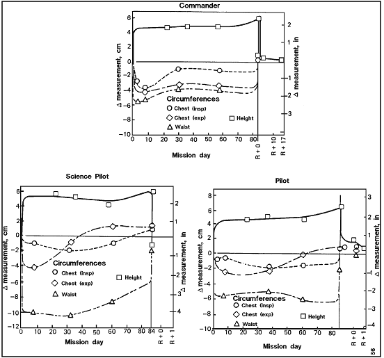
Reference: 16,
Figure 19 and 20, pp. 1-28 and 29; NASA-STD-3000 266
3.2.3.2 Inter-Individual Variation Design Considerations
{A}
The two major factors of inter-individual variations are
sex and race. The following general rules apply to the anthropometric
variations due to sex and race:
a. Sex Variations - Female measurements average about 92%
of comparable male measurements (within race). Average female
weight is about 75% of male weight.
b. Racial Variations - Blacks and Whites are very similar
in terms of height and weight measurements. The average
torso measurement of Whites is longer than Blacks and limbs
are shorter. Asians are generally shorter and lighter than
Whites and Blacks. Most of this stature difference is in
leg length. Asian facial dimensions may be larger in proportion
to height.
Because of these variations, the extremes of the world
population size range is represented in this document by
the large (95th percentile) White or Black American male
and the small (5th percentile) Asian Japanese female.
3.2.3.3 Secular Changes Design Considerations
{A}
For typical long-term space module design studies, it is
appropriate to estimate the body dimensions of a future
population of crew, passengers, and even the ground crew.
Past experience has demonstrated that there is a historical
change in average height, arm length, weight, and many other
dimensions. This type of human variation, occurring from
generation to generation over time, is usually referred
to as secular change. Whether the effect results from better
nutrition, improved health care, or some biological selection
process has not been determined.
The validity of the design requirements for the actual
operational years of the space module depends on the accuracy
of the secular trend estimation, the basic assumptions concerning
the baseline crew population, and the operational life of
the system.
For this standard, an operational year of 2000 and a crewmember
age of 40 years has been selected. The secular growth rates
of stature used to predict the year 2000 population are
shown in Figure 3.2.3.3-1.
These secular growth trends must be validated periodically.
Figure
3.2.3.3-1 Assumed Secular Growth Rate of Stature
| STATURE SECULAR
GROWTH RATE (per decade) |
| American male |
1.0 cm (0.4 in) |
| Japanese female |
2.6 cm (1.0 in) |
References: 16,
pp. III-85; 308,
Table 2; NASA-STD-3000 267
3.3
ANTHROPOMETRIC AND BIOMECHANICS RELATED DESIGN DATA
{A}
3.3.1
Body Size
{A}
3.3.1.1
Introduction
{A}
This section provides specific body distances, dimensions,
contours, and techniques for use in developing design requirements.
There is no attempt to include all potentially useful anthropometric
data in this document because much of these data are already
available in convenient published form such as Reference
16. Rather,
one description set of the size range for the projected
crewmember population is presented
The dimensions apply to nude or lightly clothed persons.
(Refer to
Paragraph 14.3, EVA Anthropometry, for dimensions for
crewmembers wearing space suits).
3.3.1.2
Body Size Design Considerations
{A}
The following are considerations that should be made in
applying the body size data:
a. Effects of Clothing - In a controlled IVA environment
there is little need for heavy, thick clothing. For most
practical purposes, therefore, there is no need to consider
the effect of IVA clothing on body size. When an individual
must wear an EVA pressure garment or a space suit, body
dimensions will be affected drastically. In this case, dimensional
studies must be made for the user population wearing the
garment. These data must then be substituted for unclothed
or lightly clothed dimensions.
b. Microgravity - the dimensions in
Paragraph 3.3.1.3 apply to 1-G conditions only. Notations
are made on appropriate dimensions that provide guidelines
for estimating microgravity dimensions.
(Refer to
Paragraph 3.2.3.1, Microgravity Effects Design Considerations,
for more detailed discussion of microgravity effects).
3.3.1.3
Body Size Data Design Requirements
{A}
Dimensions of the year 2000, 40 year-old White or Black
American male and the 40 year-old Asian Japanese female
are given in Figure 3.3.1.3-1.
The data in this figure shall be used as appropriate to
achieve effective integrations of the crew and space systems.
The dimensions apply to 1-G conditions only.
Dimensional data estimates for the year 2000 White or Black
American female crewmember cannot be specified at this time
due to insufficient data.
(Refer to Reference 16,
Chapter III, Appendix B, for dimensional data for the 1985
American female).
Figure
3.3.1.3-1 (1 of 12) Anthropometric Dimensional Data
for American Female
Body Size of the 40-Year-Old Japanese Female for Year 2000
in One Gravity Conditions
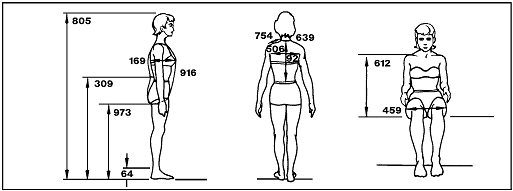
|
| Microgravity notes |
No. |
Dimension |
5th percentile |
50th percentile |
95th percentile |
| 1 |
805 |
Stature |
148.9 (58.6) |
157.0 (61.8) |
165.1 (65.0) |
| 1 |
973 |
Wrist height |
70.8 (27.9) |
76.6 (30.2) |
82.4 (32.4) |
|
64 |
Ankle height |
5.2 (2.0) |
6.1 (2.4) |
7.0 (2.8) |
| 1 |
309 |
Elbow height |
92.8 (38.5) |
98.4 (38.8) |
104.1 (41.0) |
|
169 |
Bust depth |
17.4 (6.8) |
20.5 (8.1) |
23.6 (9.3) |
| 1 |
916 |
Vertical trunk circumference |
136.9 (53.9) |
146.0 (57.5) |
155.2 (61.1) |
| 2 1 |
612 |
Midshoulder height, sitting |
|
|
|
|
459 |
Hip breadth, sitting |
30.4 (12.0) |
33.7 (13.3) |
37.0 (14.6) |
| 1 |
921 |
Waist back |
35.2 (13.9) |
38.1 (15.0) |
41.0 (16.1) |
|
506 |
Interscye |
32.4 (12.8) |
35.7 (14.1) |
39.0 (15.4) |
|
639 |
Neck circumference |
34.5 (13.6) |
37.1 (14.5) |
39.7 (15.6) |
|
754 |
Shoulder length |
11.3 (4.4) |
13.1 (5.1) |
14.8 (5.8) |
| Values in cm with inches
in parentheses
Notes:
a) Gravity conditions - the dimensions apply to
a 1-G condition only. Dimension expected to change
significantly due to microgravity are marked.
b) Measurement data - the numbers adjacent to each
of the dimension are reference codes. the same codes
are in Volume II of Reference 16.
Reference 16,
Volume II, provides additional data for these measurements
plus an explanation of the measurement technique.
Notes for application of dimensions to microgravity
conditions:
1) Stature increases approximately 3% over the first
3 to 4 days in weightlessness (see
figure 3.2.3.1-2). Almost all of this change appear
in the spinal column, and thus affects (increases)
other related dimensions, such as sitting height (buttock-vertex),
shoulder height- sitting, eye height, sitting, and
all dimensions that include the spine.
2) Sitting height would be better named as buttock-vertex
in microgravity conditions, unless the crewmember
were measured with a firm pressure on shoulders pressing
him or her against a fixed, flat "sitting"
support surface. All sitting dimensions (vertex, eye,
shoulder, and elbow) increase in weightlessness by
two changes:
a) Relief of pressure on the buttock surfaces (estimated
increase of 1.3 to 2.0 cm (0.5 to 0.8 inches).
b) Extension of the spinal column as explained
in note (1) above (3% of stature on ground).
|
Reference: 274
p. 121-128; 308;
351; NASA-STD-3000
268
Figure 3.3.1.3-1 (2 of 12) Anthropometric Dimensional
Data for American Male
Body Size of the 40-Year-Old American Male for Year 2000
in One Gravity Conditions
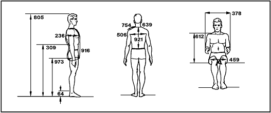 |
| Microgravity notes |
No. |
Dimension |
5th percentile |
50th percentile |
95th percentile |
| 1 |
805 |
Stature |
169.7 (66.8) |
179.9 (70.8) |
190 1 (74.8) |
| 1 |
973 |
Wrist height |
|
|
|
|
64 |
Ankle height |
12.0 (4.7) |
13.9 (5.5) |
15.8 (6.2) |
| 1 |
309 |
Elbow height |
|
|
|
|
236 |
Bust depth |
21.8 (8.6) |
25.0 (9.8) |
28.2 (11.1) |
| 1 |
916 |
Vertical trunk circumference |
158.7 (62.5) |
170.7 (67.2) |
182.6 (71.9) |
| 2 1 |
612 |
Midshoulder height, sitting |
60.8 (23.9) |
65.4 (25.7) |
70.0 (27.5) |
|
459 |
Hip breadth, sitting |
34.6 (13.6) |
38.4 (15.1) |
42.3 (16.6) |
| 1 |
921 |
Waist back |
43.7 (17.2) |
47.6 (18.8) |
51.6 (20.3) |
|
506 |
Interscye |
32.9 (13.0) |
39.2 (15.4) |
45.4 (17.9) |
|
639 |
Neck circumference |
35.5 (14.0) |
38.7 (15.2) |
41.9 (16.5) |
|
754 |
Shoulder length |
14.8 (5.8) |
16.9 (6.7) |
19.0 (7.5) |
|
378 |
Forearm-forearm breadth |
48.8 (19.2) |
55.1 (21.7) |
61.5 (24.2) |
| Values in cm with inches
in parentheses
Notes:
a) Gravity conditions - the dimensions apply to
a 1-G condition only. Dimension expected to change
significantly due to microgravity are marked.
b) Measurement data - the numbers adjacent to each
of the dimension are reference codes. the same codes
are in Volume II of Reference 16.
Reference 16, Volume II, provides additional data
for these measurements plus an explanation of the
measurement technique.
Notes for application of dimensions to microgravity
conditions:
1) Stature increases approximately 3% over the first
3 to 4 days in weightlessness (see
figure 3.2.3.1-2). Almost all of this change appear
in the spinal column, and thus affects (increases)
other related dimensions, such as sitting height (buttock-vertex),
shoulder height- sitting, eye height, sitting, and
all dimensions that include the spine.
2) Sitting height would be better named as buttock-vertex
in microgravity conditions, unless the crewmember
were measured with a firm pressure on shoulders pressing
him or her against a fixed, flat "sitting"
support surface. All sitting dimensions (vertex, eye,
shoulder, and elbow) increase in weightlessness by
two changes:
a) Relief of pressure on the buttock surfaces (estimated
increase of 1.3 to 2.0 cm (0.5 to 0.8 inches).
b) Extension of the spinal column as explained
in note (1) above (3% of stature on ground).
|
Reference: 274
p. 121-128; 308;
351; NASA-STD-3000
268
Figure 3.3.1.3-1 (3 of 12) Anthropometric Dimensional
Data for American Female
Body Size of the 40-Year-Old Japanese Female for Year 2000
in One Gravity Conditions
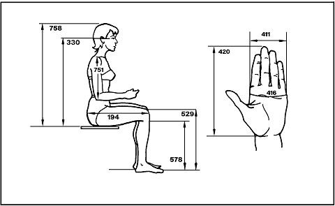
|
| Microgravity notes |
No. |
Dimension |
5th percentile |
50th percentile |
95th percentile |
| 2 1 |
758 |
Sitting height |
78.3 (30.8) |
84.8 (33.4) |
91.2 (35.9) |
| 2 1 |
330 |
Eye height, sitting |
68.1 (26.8) |
73.8 (29.1) |
79.5 (31.4) |
| 4 |
529 |
Knee height, sitting |
41.6 (16.4) |
45.6 (17.9) |
49.5 (19.5) |
|
678 |
Popliteal height |
34.7 (13.6) |
38.3 (15.1) |
41.9 (16.5) |
|
751 |
Shoulder-elbow length |
27.2 (10.7) |
29.8 (11.7) |
32.4 (12.8) |
|
194 |
Buttock-knee length |
48.9 (19.2) |
53.3 (21.0) |
57.8 (22.7) |
|
420 |
Hand length |
15.8 (6.2) |
17.2 (6.8) |
18.7 (7.3) |
|
411 |
Hand breadth |
6.9 (2.7) |
7.8 (3.1) |
8.6 (3.4) |
|
416 |
Hand circumference |
16.5 (6.5) |
17.9 (7.0) |
19.3 (7.6) |
| Notes:
a) Gravity conditions - the dimensions apply to
a 1-G condition only. Dimension expected to change
significantly due to microgravity are marked.
b) Measurement data - the numbers adjacent to each
of the dimension are reference codes. the same codes
are in Volume II of Reference 16.
Reference 16,
Volume II, provides additional data for these measurements
plus an explanation of the measurement technique.
Notes for application of dimensions to microgravity
conditions:
1) Stature increases approximately 3% over the first
3 to 4 days in weightlessness (see
figure 3.2.3.1-2). Almost all of this change appear
in the spinal column, and thus affects (increases)
other related dimensions, such as sitting height (buttock-vertex),
shoulder height- sitting, eye height, sitting, and
all dimensions that include the spine.
2) Sitting height would be better named as buttock-vertex
in microgravity conditions, unless the crewmember
were measured with a firm pressure on shoulders pressing
him or her against a fixed, flat "sitting"
support surface. All sitting dimensions (vertex, eye,
shoulder, and elbow) increase in weightlessness by
two changes:
a) Relief of pressure on the buttock surfaces (estimated
increase of 1.3 to 2.0 cm (0.5 to 0.8 inches).
b) Extension of the spinal column as explained
in note (1) above (3% of stature on ground).
4) Knee height - sitting may increase slightly in
microgravity due to relief of the pressure on the
heel which it occurs when it measured on the ground.
The increase is probably not more than 2 to 3 mm (0.1
inch). |
Reference: 274
p. 121-128; 308;
351; NASA-STD-3000
268
Figure 3.3.1.3-1 (4 of 12) Anthropometric Dimensional
Data for American Male
Body Size of the 40-Year-Old American Male for Year 2000
in One Gravity Conditions
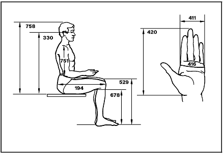
|
| Microgravity notes |
No. |
Dimension |
5th percentile |
50th percentile |
95th percentile |
| 2 1 |
758 |
Sitting height |
88.9 (35.0) |
94.2 (37.1) |
99.5 (39.2) |
| 2 1 |
330 |
Eye height, sitting |
76.8 (30.3) |
81.9 (32.2) |
86.9 (34.2) |
| 4 |
529 |
Knee height, sitting |
52.6 (20.7) |
56.7 (22.3) |
60.9 (24.0) |
|
678 |
Popliteal height |
40.6 (16.0) |
44.4 (17.5) |
48.1 (19.0) |
|
751 |
Shoulder-elbow length |
33.7 (13.3) |
36.6 (14.4) |
39.4 (15.5) |
|
194 |
Buttock-knee length |
56.8 (22.4) |
61.3 (24.1) |
65.8 (25.9) |
|
420 |
Hand length |
17.9 (7.0) |
19.3 (7.6) |
20.6 (8.1) |
|
411 |
Hand breadth |
8.2 (3.2) |
8.9 (3.5) |
9.6 (3.8) |
|
416 |
Hand circumference |
20.3 (8.0) |
21.8 (8.6) |
23.4 (9.2) |
| Notes:
a) Gravity conditions - the dimensions apply to
a 1-G condition only. Dimension expected to change
significantly due to microgravity are marked.
b) Measurement data - the numbers adjacent to each
of the dimension are reference codes. the same codes
are in Volume II of Reference 16.
Reference 16,
Volume II, provides additional data for these measurements
plus an explanation of the measurement technique.
Notes for application of dimensions to microgravity
conditions:
1) Stature increases approximately 3% over the first
3 to 4 days in weightlessness (see
figure 3.2.3.1-2). Almost all of this change appear
in the spinal column, and thus affects (increases)
other related dimensions, such as sitting height (buttock-vertex),
shoulder height- sitting, eye height, sitting, and
all dimensions that include the spine.
2) Sitting height would be better named as buttock-vertex
in microgravity conditions, unless the crewmember
were measured with a firm pressure on shoulders pressing
him or her against a fixed, flat "sitting"
support surface. All sitting dimensions (vertex, eye,
shoulder, and elbow) increase in weightlessness by
two changes:
a) Relief of pressure on the buttock surfaces (estimated
increase of 1.3 to 2.0 cm (0.5 to 0.8 inches).
b) Extension of the spinal column as explained
in note (1) above (3% of stature on ground).
4) Knee height - sitting may increase slightly in
microgravity due to relief of the pressure on the
heel which it occurs when it measured on the ground.
The increase is probably not more than 2 to 3 mm (0.1
inch). |
Reference: 274,
pp. 121-128; 308;
351; NASA-STD-3000
268
Figure 3.3.1.3-1 (5 of 12) Anthropometric Dimensional
Data for American Female
Body Size of the 40-Year-Old Japanese Female for Year 2000
in One Gravity Conditions
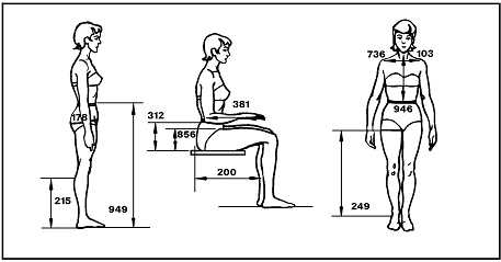
|
| Microgravity notes |
No. |
Dimension |
5th percentile |
50th percentile |
95th percentile |
|
949 |
Waist height |
90.1 (35.5) |
96.7 (38.1) |
103.4 (40.7) |
|
249 |
Crotch height |
65.2 (25.7) |
70.6 (27.8) |
76.1 (30.0) |
|
215 |
Calf height |
25.5 (10.0) |
28.9 (11.4) |
32.3 (12.7) |
|
103 |
Biacromial breadth |
32.4 (12.8) |
35.7 (14.1) |
39.0 (15.4) |
| 1 |
946 |
Waist front |
|
|
|
|
735 |
Scye circumference |
32.3 (12.7) |
36.1 (14.2) |
39.8 (15.7) |
|
178 |
Buttock circumference |
79.9 (31.5) |
87.1 (34.3) |
94.3 (37.1) |
| 1 2 |
312 |
Elbow rest height |
20.7 (8.2) |
25.0 (9.9) |
29.3 (11.5) |
|
856 |
Thigh clearance |
11.2 (4.4) |
12.9 (5.1) |
14.5 (5.7) |
|
381 |
Forearm hand length |
37.3 (14.7) |
41.7 (16.4) |
44.6 (17.6) |
|
200 |
Buttock-popliteal length |
37.9 (14.9) |
41.7 (16.4) |
45.5 (17.9) |
| Values in cm with inches in parentheses
Notes:
a) Gravity conditions - the dimensions apply to
a 1-G condition only. Dimension expected to change
significantly due to microgravity are marked.
b) Measurement data - the numbers adjacent to each
of the dimension are reference codes. the same codes
are in Volume II of Reference 16.
Reference 16,
Volume II, provides additional data for these measurements
plus an explanation of the measurement technique.
Notes for application of dimensions to microgravity
conditions:
1) Stature increases approximately 3% over the first
3 to 4 days in weightlessness (see
figure 3.2.3.1-2). Almost all of this change appear
in the spinal column, and thus affects (increases)
other related dimensions, such as sitting height (buttock-vertex),
shoulder height- sitting, eye height, sitting, and
all dimensions that include the spine.
2) Sitting height would be better named as buttock-vertex
in microgravity conditions, unless the crewmember
were measured with a firm pressure on shoulders pressing
him or her against a fixed, flat "sitting"
support surface. All sitting dimensions (vertex, eye,
shoulder, and elbow) increase in weightlessness by
two changes:
a) Relief of pressure on the buttock surfaces (estimated
increase of 1.3 to 2.0 cm (0.5 to 0.8 inches).
b) Extension of the spinal column as explained
in note (1) above (3% of stature on ground).
|
Reference: 274,
pp. 121-128; 308;
351; NASA-STD-3000
268eT
Figure 3.3.1.3-1 ( 6 of 12) Anthropometric Dimensional
Data for American Male
Body Size of the 40-Year-Old American Male for Year 2000
in One Gravity Conditions
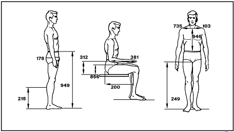
|
| Microgravity notes |
No. |
Dimension |
5th percentile |
50th percentile |
95th percentile |
|
949 |
Waist height |
100.4 (39.5)) |
108.3 (42.6) |
116.2 (45.7) |
|
249 |
Crotch height |
79.4 (31.3) |
86.4 (34.0) |
93.3 (36.7) |
|
215 |
Calf height |
32.5 (12.8) |
36.2 (14.3) |
40.0 (15.7) |
|
103 |
Biacromial breadth |
37.9 (14.9) |
41.1 (16.2) |
44.3 (17.5) |
| 1 |
946 |
Waist front |
37.2 (14.6) |
40.9 (16.1) |
44.5 (17.5) |
|
735 |
Scye circumference |
44.4 (17.5) |
49.0 (19.3) |
53.6 (21.1) |
|
178 |
Buttock circumference |
91.0 (35.8) |
100.2 (39.4) |
109.4 (43.1) |
| 1 2 |
312 |
Elbow rest height |
21.1 (8.3) |
25.4 (10.0) |
29.7 (11.7) |
|
856 |
Thigh clearance |
14.5 (5.7) |
16.8 (6.6) |
19.1 (7.5) |
|
381 |
Forearm hand length |
|
|
|
|
200 |
Buttock popliteal length |
46.9 (18.5) |
51.2 (20.2) |
55.5 (21.9) |
| Notes:
a) Gravity conditions - the dimensions apply to
a 1-G condition only. Dimension expected to change
significantly due to microgravity are marked.
b) Measurement data - the numbers adjacent to each
of the dimension are reference codes. the same codes
are in Volume II of Reference 16.
Reference 16,
Volume II, provides additional data for these measurements
plus an explanation of the measurement technique.
Notes for application of dimensions to microgravity
conditions:
1) Stature increases approximately 3% over the first
3 to 4 days in weightlessness (see
figure 3.2.3.1-2). Almost all of this change appear
in the spinal column, and thus affects (increases)
other related dimensions, such as sitting height (buttock-vertex),
shoulder height- sitting, eye height, sitting, and
all dimensions that include the spine.
2) Sitting height would be better named as buttock-vertex
in microgravity conditions, unless the crewmember
were measured with a firm pressure on shoulders pressing
him or her against a fixed, flat "sitting"
support surface. All sitting dimensions (vertex, eye,
shoulder, and elbow) increase in weightlessness by
two changes:
a) Relief of pressure on the buttock surfaces (estimated
increase of 1.3 to 2.0 cm (0.5 to 0.8 inches).
b) Extension of the spinal column as explained
in note (1) above (3% of stature on ground).
|
Reference: 274,
pp. 121-128; 308;
351; NASA-STD-3000
268eT
Figure 3.3.1.3-1 (7 of 12) Anthropometric Dimensional
Data for American Female
Body Size of the 40-Year-Old Japanese Female for Year 2000
in One Gravity Conditions
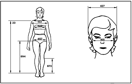
|
| Microgravity notes |
No. |
Dimension |
5th percentile |
50th percentile |
95th percentile |
| 3, 1 |
23 |
Acromial (shoulder) height |
119.6 (47.1) |
127.1 (50.0) |
134.5 (53.0) |
|
894 |
Trochanteric height |
71.0 (28.0) |
76.7 (30.2) |
82.4 (32.5) |
|
873 |
Tibiale height |
35.9 (14.1) |
39.3 (15.5) |
42.7 (16.8) |
|
122 |
Bideltoid (shoulder) breadth |
35.6 (14.0) |
38.9 (15.3) |
42.1 (16.6) |
|
223 |
Chest breadth |
24.5 (9.7) |
26.8 (10.5) |
29.0 (11.4) |
|
457 |
Hip breadth |
30.5 (12.0) |
32.9 (12.9) |
35.3 (13.9) |
|
165 |
Bizgomatic (face) breadth |
13.3 (5.2) |
14.5 (5.7) |
15.7 (6.2) |
|
427 |
Head breadth |
14.4 (5.7) |
15.6 (6.1) |
16.8 (6.6) |
| Values in cm with inches in parentheses
Notes:
a) Gravity conditions - the dimensions apply to
a 1-G condition only. Dimension expected to change
significantly due to microgravity are marked.
b) Measurement data - the numbers adjacent to each
of the dimension are reference codes. the same codes
are in Volume II of Reference 16.
Reference 16,
Volume II, provides additional data for these measurements
plus an explanation of the measurement technique.
Notes for application of dimensions to microgravity
conditions:
1) Stature increases approximately 3% over the first
3 to 4 days in weightlessness (see
figure 3.2.3.1-2). Almost all of this change appear
in the spinal column, and thus affects (increases)
other related dimensions, such as sitting height (buttock-vertex),
shoulder height-sitting, eye height, sitting, and
all dimensions that include the spine.
3) Shoulder or acromial, height, sitting or standing,
increases during weightlessness due to two factors:
a) Removal of the gravitational pull on the arms
b) Extension of the spinal column as explained
in note (1) above 3% of stature on ground).
|
Reference: 274;
pp. 121-128; 308;
351; NASA-STD-3000
268pT
Figure 3.3.1.3-1 (8 of 12) Anthropometric Dimensional
Data for American Male
Body Size of the 40-Year-Old American Male for Year 2000
in One Gravity Conditions
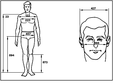 |
| Microgravity notes |
No. |
Dimension |
5th percentile |
50th percentile |
95th percentile |
| 3 1 |
23 |
Acromial (shoulder) height |
138.0 (54.3) |
147.6 (58.1) |
157.3 (61.9) |
|
894 |
Trochanteric height |
88.3 (34.8) |
95.8 (37.8) |
102.9 (40.5) |
|
873 |
Tibiale height |
|
|
|
|
122 |
Bideltoid (shoulder) breadth |
44.6 (17.6) |
48.9 (19.3) |
53.2 (20.9) |
|
223 |
Chest breadth |
29.7 (11.7) |
33.2 (13.1) |
36.7 (14.4) |
|
457 |
Hip breadth |
32.7 (12.9) |
35.8 (14.1) |
39.0 (15.4) |
|
165 |
Bizgomatic (face) breadth |
13.4 (5.3) |
14.3 (5.6) |
15.1 (6.0) |
|
427 |
Head breadth |
14.8 (5.8) |
15.7 (6.2) |
16.5 (6.5) |
| Values in cm with inches in parentheses
Notes:
a) Gravity conditions - the dimensions apply to
a 1-G condition only. Dimension expected to change
significantly due to microgravity are marked.
b) Measurement data - the numbers adjacent to each
of the dimension are reference codes. the same codes
are in Volume II of Reference 16.
Reference 16,
Volume II, provides additional data for these measurements
plus an explanation of the measurement technique.
Notes for application of dimensions to microgravity
conditions:
1) Stature increases approximately 3% over the first
3 to 4 days in weightlessness (see
figure 3.2.3.1-2). Almost all of this change appear
in the spinal column, and thus affects (increases)
other related dimensions, such as sitting height (buttock-vertex),
shoulder height-sitting, eye height, sitting, and
all dimensions that include the spine.
3) Shoulder or acromial, height, sitting or standing,
increases during weightlessness due to two factors:
a) Removal of the gravitational pull on the arms
b) Extension of the spinal column as explained
in note ( 1) above 3% of stature on ground).
|
Reference: 274,
pp. 121-128; 308;
351; NASA-STD-3000
268hT
Figure 3.3.1.3-1 (9 of 12) Anthropometric Dimensional
Data for American Female
Body Size of the 40-Year-Old Japanese Female for Year 2000
in One Gravity Conditions
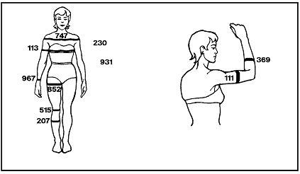
|
| Microgravity notes |
No. |
Dimension |
5th percentile |
50th percentile |
95th percentile |
|
747 |
Shoulder circumference |
|
|
|
|
230 |
Chest circumference |
73.2 (28.8) |
82.1 (32.3) |
90.9 (35.8) |
| 6 |
931 |
Waist circumference |
55.3 (21.8) |
63.2 (24.9) |
71.2 (28.0) |
| 5 |
852 |
Thigh circumference |
45.6 (17.9) |
51.6 (20.3) |
57.7 (22.7) |
| 5 |
515 |
Knee circumference |
31.0 (12.2) |
34.6 (13.6) |
38.2 (15.0) |
| 5 |
207 |
Calf circumference |
30.3 (11.9) |
34.1 (13.4) |
37.8 (14.9) |
|
113 |
Biceps circumference, relaxed |
21.8 (8.6) |
25.5 (10.1) |
29.3 (11.5) |
|
967 |
Wrist circumference |
13.7 (5.4) |
15.0 (5.9) |
16.2 (6.4) |
|
111 |
Biceps circumference, flexed |
|
|
|
|
369 |
Forearm circumference, relaxed |
19.9 (7.8) |
22.0 (8.7) |
24.1 (9.5) |
| Values in cm with inches in parentheses
Notes:
a) Gravity conditions - the dimensions apply to
a 1-G condition only. Dimension expected to change
significantly due to microgravity are marked.
b) Measurement data - the numbers adjacent to each
of the dimension are reference codes. the same codes
are in Volume II of Reference 16.
Reference 16,
Volume II, provides additional data for these measurements
plus an explanation of the measurement technique.
Notes for application of dimensions to microgravity
conditions:
5) Leg circumferences and diameters significantly
decrease during the first day in microgravity. See
Reference 16,
Appendix C, for details and measurements of actual
persons.
6) Waist circumference will decrease in microgravity
due to fluid shifts to the upper torso. See
figure 3.2.3.1-2 for measurements on actual persons.
|
Reference: 274,
pp. 121-128; 308;
351; NASA-STD-3000
268iT, 268q
Figure 3.3.1.3-1 (10 of 12) Anthropometric Dimensional
Data for American Male
Body Size of the 40-Year-Old American Male for Year 2000
in One Gravity Conditions
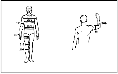 |
| Microgravity notes |
No. |
Dimension |
5th percentile |
50th percentile |
95th percentile |
|
747 |
Shoulder circumference |
109.5 (43.1) |
119.2 (46.9) |
128.8 (50.7) |
|
230 |
Chest circumference |
89.4 (35.2) |
100.0 (39.4) |
110.6 (43.6) |
| 6 |
931 |
Waist circumference |
77.1 (30.3) |
89.5 (35.2) |
101.9 (40.1) |
| 5 |
852 |
Thigh circumference |
52.5 (20.7) |
60.0 (23.6) |
67.4 (26.5) |
| 5 |
515 |
Knee circumference |
35.9 (14.1) |
39.4 (15.5) |
42.9 (16.9) |
| 5 |
207 |
Calf circumference |
33.9 (13.3) |
37.6 (14.8) |
41.4 (16.3) |
|
113 |
Biceps circumference, relaxed |
27.3 (10.7) |
31.2 (12.3) |
35.1 (13.8) |
|
967 |
Wrist circumference |
16.2 (6.4) |
17.7 (7.0) |
19.3 (7.6) |
|
111 |
Biceps circumference, flexed |
29.4 (11.6) |
33.2 (13.1) |
36.9 (14.5) |
|
369 |
Forearm circumference, relaxed |
27.4 (10.8) |
30.1 (11.8) |
32.7 (12.9) |
| Notes:
a) Gravity conditions - the dimensions apply to
a 1-G condition only. Dimension expected to change
significantly due to microgravity are marked.
b) Measurement data - the numbers adjacent to each
of the dimension are reference codes. the same codes
are in Volume II of Reference 16.
Reference 16,
Volume II, provides additional data for these measurements
plus an explanation of the measurement technique.
Notes for application of dimensions to microgravity
conditions:
5) Leg circumferences and diameters significantly
decrease during the first day in microgravity. See
Reference 16,
Appendix C, for details and measurements of actual
persons.
6) Waist circumference will decrease in microgravity
due to fluid shifts to the upper torso. See
figure 3.2.3.1-2 for measurements on actual persons.
|
Reference: 274,
pp. 121-128; 308;
351; NASA-STD-3000
368
Figure 3.3.1.3-1 (11 of 12) Anthropometric Dimensional
Data for American Female
Body Size of the 40-Year-Old Japanese Female for Year 2000
in One Gravity Conditions
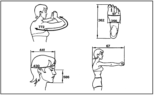 |
| Microgravity notes |
No. |
Dimension |
5th percentile |
50th percentile |
95th percentile |
|
67 |
Thumb-tip reach |
65.2 (25.7) |
71.6 (28.2) |
78.0 (30.7) |
|
772 |
Sleeve length |
|
|
|
|
441 |
Head length |
16.7 (6.6) |
18.2 (7.2) |
19.6 (7.7) |
|
430 |
Head circumference |
53.2 (20.9) |
55.2 (21.7) |
57.2 (22.5) |
|
586 |
Menton-sellion (face) length |
9.0 (3.5) |
10.8 (4.2) |
12.6 (5.0) |
|
362 |
Foot length |
21.3 (8.4) |
22.9 (9.0) |
24.4 (9.6) |
|
356 |
Foot breadth |
8.6 (3.4) |
9.3 (3.7) |
10.0 (3.9) |
|
97 |
Ball of foot circumference |
21.0 (8.3) |
22.7 (8.9) |
24.3 (9.6) |
| Values in cm with inches in parentheses
Notes:
a) Gravity conditions - the dimensions apply to a
1-G condition only. Dimension expected to change significantly
due to microgravity are marked.
b) Measurement data - the numbers adjacent to each
of the dimension are reference codes. the same codes
are in Volume II of Reference 16.
Reference 16,
Volume II, provides additional data for these measurements
plus an explanation of the measurement technique. |
Reference: 274,
pp. 121-128; 308;
351; NASA-STD-3000
268k
Figure 3.3.1.3-1 (12 of 12) Anthropometric Dimensional
Data for American Male
Body Size of the 40-Year-Old American Male for Year 2000
in One Gravity Conditions
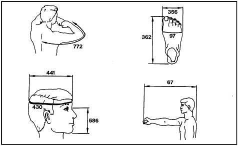 |
| Microgravity notes |
No. |
Dimension |
5th percentile |
50th percentile |
95th percentile |
|
67 |
Thumb-tip reach |
74.9 (29.5) |
81.6 (32.1) |
88.2 (34.7) |
|
772 |
Sleeve length |
86.2 (33.9) |
92.0 (36.2) |
97.9 (38.5) |
|
441 |
Head length |
18.8 (7.4) |
20.0 (7.9) |
21.1 (8.3) |
|
430 |
Head circumference |
55.5 (21.8) |
57.8 (22.8) |
60.2 (23.7) |
|
586 |
Menton-sellion (face) length |
11.1 (4.4) |
12.1 (4.8) |
13.1 (5.2) |
|
362 |
Foot length |
25.4 (10.0) |
27.3 (10.8) |
29.3 (11.5) |
|
356 |
Foot breadth |
9.0 (3.6) |
9.9 (3.9) |
10.7 (4.2) |
|
97 |
Ball of foot circumference |
23.1 (9.1) |
25.1 (9.9) |
27.2 (10.7) |
| Values in cm with inches in parentheses
Notes:
a) Gravity conditions - the dimensions apply to
a 1-G condition only. Dimension expected to change
significantly due to microgravity are marked.
b) Measurement data - the numbers adjacent to each
of the dimension are reference codes. the same codes
are in Volume II of Reference 16.
Reference 16,
Volume II, provides additional data for these measurements
plus an explanation of the measurement technique.
|
Reference: 274,
pp. 121-128; 308;
351; NASA-STD-3000
268L
3.3.2 Joint
Motion
{A}
This section provides information for developing design
requirements related to biomechanics, particularly skeletal
joint angular motion capabilities and limitations. Joint
motion data can be used to determine possible positions
for the various parts of body.
(Refer to Paragraph 3.3.3, Reach,
for functional reach data).
3.3.2.1 Introduction
{A}
3.3.2.2 Joint Motion Design Considerations
{A}
3.3.2.2.1 Application of Data Design Considerations
{A}
Joint motion capability varies throughout the population.
The values given are for the 5th and 95th percentile of
the range. The data should be applied in the following manner:
a. 5th Percentile - Use the 5th percentile limit when personnel
must position their body to operate or maintain equipment.
b. 95th Percentile - Use the 95th percentile limit when
designing to accommodate a full range of unrestricted movement.
Unless the equipment in the workspace is sex-specific (i.e.,
used by only males or by only females), then the designer
should consider the upper and lower limits for the combined
male and female population. In general, the female population
has a slightly broader range of joint movement.
3.3.2.2.2 Multi-Joint Versus Single Joint Data Design
Consideration
{A}
More often than not, human motion involves interaction
of two or more joints and muscles. The movement range of
a single joint is often drastically reduced by the movement
of an adjacent joint. In other words, joint movement ranges
are not always additive. For example, an engineering layout
may show (using a scaled manikin) that a foot control is
reachable with a hip flexion of 50 degrees and the knee
extended (0 degrees flexion). Both of these ranges are within
the individual joint ranges as shown in
Figure 3.3.2.3.1-1. However,
Figure 3.3.2.3.2-1 shows the hip flexion is reduced
by over 30 degrees when the knee is extended. The control
would, therefore, not be reachable.
3.3.2.2.3 Gravity Environment Design Considerations
{A}
The joint motion studies were performed in a 1-G environment.
There are no data for the microgravity environment. Indications
are that joint motion capability will not be drastically
affected in microgravity. Given this, the data in this section
can be applied to a microgravity environment.
3.3.2.3 Joint Motion Data Design Requirements
{A}
3.3.2.3.1 Joint Motion Data For Single Joint Design Requirements
{A}
Figure 3.3.2.3.1-1 shows
single joint movement ranges for both males and females.
These data apply to both 1-G and microgravity environments.
These data shall be used as appropriate to ensure the design
accommodates the required body movements for the crewmembers.
Figure
3.3.2.3.1-1 Joint Movement Ranges for Males and Females
| Figure |
Joint movement
(note b) |
Range of motion (degrees) |
| Males (note a) |
Female (note a) |
| 5th percentile |
95th percentile |
5th percentile |
95th percentile |
| 1
.gif)
|
Neck, rotation right (A) |
73.3 |
99.6 |
74.9 |
108.8 |
| Neck, rotation left (B) |
74.3 |
99.1 |
72.2 |
109.0 |
| 2
.gif) |
Neck, flexion (B) |
34.5 |
71.0 |
46.0 |
84.4 |
| Neck, extension (A) |
65.4 |
103.0 |
4.9 |
103.0 |
| 3
.gif)
|
Neck, lateral bend right (A) |
34.9 |
63.5 |
37.0 |
63.2 |
| Neck, lateral bend left (B) |
35.5 |
63.5 |
29.1 |
77.2 |
| 4
.gif)
|
Shoulder, abduction |
173.2 |
188.7 |
172.6 |
192.9 |
| 5
.gif)
|
Shoulder, rotation lateral (A) |
46.3 |
96.7 |
53.8 |
85.8 |
| Shoulder, rotation medial (B) |
90.5 |
126.6 |
95.8 |
130.9 |
| 6
.gif)
|
Shoulder, flexion (A) |
164.4 |
210.9 |
152.0 |
217.0 |
| Shoulder, extension (B) |
39.6 |
83.3 |
33.7 |
87.9 |
| 7
.gif)
|
Elbow, flexion (A) |
140.5 |
159.0 |
144.9 |
165.9 |
| 8
.gif)
|
Forearm, pronation (B) |
78.2 |
116.1 |
82.3 |
118.9 |
| Forearm, supination (A) |
83.4 |
125.8 |
90.4 |
139.5 |
| 9
.gif)
|
Wrist, radial bend (B) |
16.9 |
36.7 |
16.1 |
36.1 |
| Wrist, ulnar bend (A) |
18.6 |
47.9 |
21.5 |
43.0 |
10
.gif) |
Wrist, flexion (A) |
61.5 |
94.8 |
68.3 |
98.1 |
| Wrist, extension (B) |
40.1 |
78.0 |
42.3 |
74.7 |
| 11
.gif) |
Hip, flexion |
116.5 |
148.0 |
118.5 |
145.0 |
| 12
.gif)
|
Hip, abduction (B) |
26.8 |
53.5 |
27.2 |
55.9 |
| 13
.gif)
|
Knee, flexion |
118.4 |
145.6 |
125.2 |
145.2 |
| 14
.gif)
|
Ankle, plantar extension (A) |
36.1 |
79.6 |
44.2 |
91.1 |
| Ankle, dorsi flexion (B) |
8.1 |
19.9 |
6.9 |
17.4 |
| Notes:
a. Data was taken 1979 and 1980 at NASA-JSC by Dr.
William Thornton and John Jackson. The study was made
using 192 males (mean age 33) 22 females (mean age
30) astronaut candidates (see
Reference 365).
b. Limb range is average of right and left limb movement. |
Reference: 365,
Figure 3, pp. 711-713; NASA-STD-3000 340A
3.3.2.3.2 Joint Motion Data For Two Joint Design Requirements
{A}
Data to determine the range of movement for two joints
are given in Figure 3.3.2.3.2-1.
Figure 3.3.2.3.2-1 defines the changes in range of motion
of a given joint when supplemented by the movement of an
adjacent joint. These data apply to both 1-G and microgravity
environments. These data shall be used as appropriate to
ensure the design accommodates the required body movements
of the crewmembers.
Figure
3.3.2.3.2-1 Change in Range of Movement With Movement
in Adjacent Joint
| Two-joint movement |
Full range of
A (degrees) |
Change in range
of movement of A (degrees) |
|
Movement of B (fraction of full range) |
| Zero |
1/3 |
1/2 |
2/3 |
Full |
| Shoulder extension (A)
with elbow flexion (B) |
59.3 deg |
|
+1.6 deg
(102.7%) |
|
+0.9 deg
(101.5%) |
+5.3 deg
(108.9%) |
| Shoulder flexion (A)
with elbow flexion (B) |
190.7 deg |
|
-24.9 deg
(86.9%) |
|
-36.1 deg
(81.0%) |
-47.4 deg
(75.0%) |
| Elbow flexion (A)
with shoulder extension (A) |
152.2 deg |
|
|
-3.78 deg
(97.5%) |
|
-1.22 deg
(99.2%) |
| Elbow flexion (A)
with shoulder flexion (B) |
152.2 deg |
|
-0.6 deg
(99.6%) |
|
-0.8 deg
(99.5%) |
-69.0 deg
(54.7%) |
| Hip flexion (A)
with shoulder flexion (B) |
53.3 deg |
-35.6 deg *
(33.2%) |
-24.0 deg
(55.0%) |
|
-6.2 deg
(88.4%) |
-12.3 deg
(76.9%) |
| Ankle plantar flexion (A)
with knee flexion (B) |
48.0 deg |
|
-3.4 deg
(92.9%) |
|
+0.2 deg
(100.4%) |
+1.6 deg
(103.3%) |
| Ankle dorsiflexion (A)
with knee flexion (B) |
26.1 deg |
|
-7.3 deg
(72.0%) |
|
-2.7 deg
(89.7%) |
-3.2 deg
(87.7%) |
| Knee flexion (A)
with ankle plantar flexion (B) |
127.0 deg |
|
|
-9.9 deg
(92.2%) |
|
-4.7 deg
(96.3%) |
| Knee flexion (A)
with ankle dorsiflexion (B) |
127.0 deg |
|
|
|
|
-8.7 deg
(93.0%) |
| Knee flexion (A)
with hip flexion (B) |
127.0 deg |
|
|
-19.6 deg
(84.6%) |
|
-33.6 deg
(73.5%) |
| Notes:
* The knee joint is locked and the unsupported leg
extends out in front of the subject.
The following is an example of how the Figure is
to be used. The first entry is as follows: the shoulder
can be extended as far as 59.3 degrees ( the mean
of the subjects tested) with the elbow in a neutral
position (locked in hyperextension). When shoulder
extension was measured with the elbow flexed to 1/3
of its full joint range, the mean value of shoulder
extension was found to increase by 1.6 degrees, or
102.7% of the base value. The results for other movements
and adjacent joint positions are presented in a similar
manner. |
Reference: 16,
pp. VI-12 to VI-15; NASA-STD-3000 289
3.3.3
Reach
{A}
3.3.3.1
Introduction
{A}
The following section discusses human body reach limits
in terms of functional reach and in terms of body strike
envelope. Body strike envelope defines the volume that the
extremities (legs, head, arms) of a seated and restrained
crewmember will strike when subjected to high accelerations
such as during launch and entry
The information in this section is limited to IVA conditions
where the crewmember is wearing nonrestrictive clothing
(Refer to
Paragraph 14.3, EVA Anthropometry, for EVA functional
reach envelopes).
3.3.3.2
Reach Design Considerations
{A}
3.3.3.2.1
Gravity Condition Design Considerations
{A}
All definitive studies of both static anthropometry and
functional reach have been made on the Earth's surface under
conditions of standard gravity. However, microgravity and
multigravity environments will affect both static anthropometry
and functional reach measurements in the following manner:
a. Microgravity Effects - The spine will lengthen under
microgravity conditions. This will increase the overhead
reach limits. Downward reaches are more difficult; there
is no gravity assist. Similarly, upward reaches will seem
easier.
(Refer to
Paragraph 3.2.3.1, Microgravity Effects Design Considerations,
for details of spinal changes in microgravity).
b. Multi-G Effects - While microgravity may be the constant
environment for some space modules, another module, such
as the Space Shuttle, may experience accelerations up to
3-G during launch and up to 1.5-G during a typical entry.
Any controls or workspace items that must be reached and
operated during these times cannot be positioned on the
basis of the greater reach capabilities in microgravity
or 1-G. The reach movement restrictions in a multi-G environment
are shown in Figure 3.3.3.2.1-1.
The designer must keep in mind that any system basically
being designed for micro-g use, if it is to be utilized
in one-g or multi-g environments, must take into account
the reduced reach capability which the user will experience
under these conditions.
c. Short Duration, Multi-G Effects - Abrupt high accelerations
can cause the extremities of even a securely restrained
crewmember flail. In this case, the designer must consider
the nonfunctional and potentially injurious aspects of the
reach envelope.
Figure
3.3.3.2.1-1 Reach Movements Possible in a Multi-G Environment
| Acceleration |
Possible Reach Motion |
| Up to 4-G |
Arm |
| Up to 5-G (9-G if arm is counter balanced) |
Forearm |
| Up to 8-G |
Hand |
| Up to 10-G |
Finger |
Reference: 19,
Section 2D6, p. 1; NASA-STD-3000 290
3.3.3.2.2
Body Posture Design Considerations
{A}
In multi-, 1-, or partial gravity environments, standing
or seated postures are commonly used for workspace operation.
In the seated posture, the reach envelope can be severely
restricted if the crewmember is wearing a fixed shoulder
harness that does not reel out. Body postures which must
be maintained for extended periods of time in 1- or multi-g
environments may result in accelerated fatigue problems;
e.g., bending over for long periods.
The normal working posture of the body in a microgravity
environment differs substantially from that in a 1-G environment.
The seated posture is, for all practical purposes, eliminated
because the sitting posture is not a natural one under these
conditions. The neutral body posture is the basic posture
that should be used in establishing a microgravity workspace
layout.
(Refer to Paragraph
3.3.4, Neutral Body Posture, for a definition of neutral
body posture).
(Refer to Paragraph 9.2.4,
Human/Workstation Configuration, for information on accommodating
the neutral body posture in the workstation).
3.3.3.2.3
Restraint Design Considerations
{O}
While the absence of gravitational forces will usually
facilitate rather than restrict body movement, this lack
of gravity will leave crewmembers without any stabilization
when they exert a thrust or push. Thus, some sort of body
restraint system is necessary. Three basic types of body
restraint or stabilizing devices have been tested either
under neutral buoyancy conditions on Earth and/or actual
microgravity conditions in space. These are handhold, waist,
and foot restraints. The following is a description of each
type of restraint and its effect on reach:
(Refer to
Paragraph 11.7.2, Personnel Restraints, for neutral
body posture restraints design information).
a. Handhold Restraint - With the handhold restraint, the
individual is stabilized by holding onto a handgrip with
one hand and performing the reach or task with the other.
This restraint affords a fairly wide range of functional
reaches, but body control is difficult and body stability
is poor.
b. Waist Restraint - A waist restraint (for example, a
clamp or belt around the waist) affords good body control
and stabilization, but seriously limits the range of motion
and reach distances attainable.
c. Foot Restraint - The third basic system restrains the
individual by the feet. In Skylab observations and neutral
buoyancy test, the foot restraints were judged to be excellent
in reach performance, stability, and control. The foot restraint
provides a large reach envelope to the front, back, and
to the sides of the crewmember. Appreciable forces can often
not be exerted due to weak muscles of the ankle rotators.
Foot restraints should be augmented with waist or other
types of restraints where appropriate.
3.3.3.2.4
Task Type Design Considerations
{A}
The length of a functional arm reach is clearly dependent
on the kind of task or operation to be performed by that
reach. For example, tasks requiring only fingertip pressure
on a pushbutton could be located at or near the outer limits
of arm reach as defined by the fingertip. This would be,
essentially, absolute maximum functional reach attainable.
However, another task may require rotation of a control
knob between thumb and forefinger; this would result in
a reduction of the above maximum attainable functional reach.
Full hand grasp of a control lever would reduce maximum
reach even more. Where two-handed operation, greater precision,
or continuous operation are required, the task must be located
still closer to the operator.
(Refer to Paragraph
9.3, Controls, for further information on types of hand
controls).
3.3.3.2.5
Clothing Design Considerations
{A}
Clothing and personal equipment worn on the body can influence
functional reach measurements. The effect is most commonly
a decrease in reach. This decrease can sometimes be considered
if clothing or equipment are especially bulky or cumbersome.
Most data on functional reaches have been gathered under
so-called light indoor clothing), which do not appreciably
affect the measurements.
If space suits are required during any phase of the space
module operations, this will necessitate a substantial reduction
in any design reach dimensions established for shirtsleeve
operations. The extent of these differences would have to
be determined from using the specific space suits and gear
to be employed in that mission. The information in this
section applies only to light, nonrestrictive clothing.
(Refer to
Paragraph 14.3, EVA Anthropometry for information on
EVA functional reach dimensions).
3.3.3.2.6
Crewmember Size Design Considerations
{A}
Crew stations should accommodate the reach limits of the
smallest crewmember. Reach limits are not always defined
by overall size, however. For instance, the worst case condition
for a constrained (e.g., seated with shoulder harness tight)
is a combination of a long shoulder height and a short arm.
These statistical variations in proportions are natural
and should be accounted for in reach limit definitions.
The reach limits in Figure
3.3.3.3.1-1 account for these variations.
3.3.3.3
Reach Data Design Requirements
{A}
3.3.3.3.1
Functional Reach Design Requirements
{A}
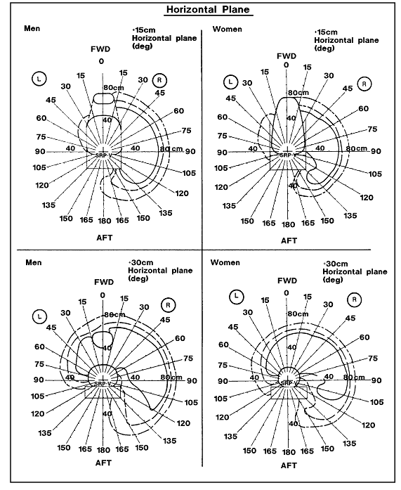
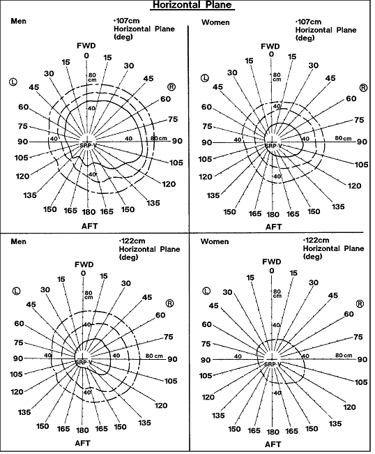
Equipment and controls required to perform a task shall
be within the reach limit of the crewmember performing the
task. The reach limit envelope cannot be considered a working
reach envelope. Reach is effected by fatigue and force exerted
and there is a marked variation in strength which can be
exerted throughout this envelope. Tasks which require strength
and dexterity should be located well within the perimeter
of the reach limit envelope. This is especially true of
repetitious tasks. For strength limitations, see Section
4.9. The following are functional reach limits for persons
wearing non-restrictive clothing:
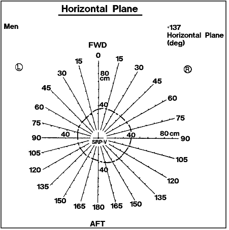
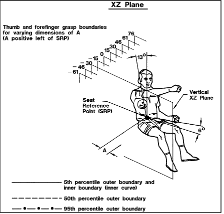
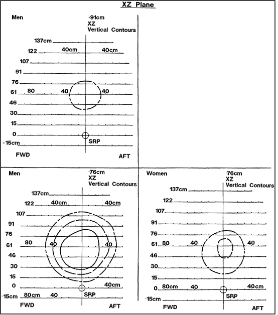
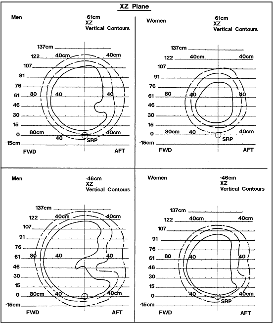
a.
Torso Restrained Reach Boundaries - Equipment and controls
operated by crewmembers restrained at the torso, shall be
within the functional reach boundaries given in
Figure 3.3.3.3.1-1. These boundaries shall be adjusted
as appropriate to the task conditions:
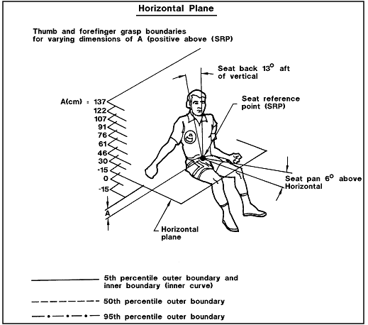
1. Backrest Angle - The boundaries in
Figure 3.3.3.3.1-1 apply when the operator's shoulders
are against a flat backrest inclined 13 degrees from vertical.
Adjustments shall be made for different backrest angles
using the approximations in
Figure 3.3.3.3.1-2.
2. Task Type - The functional reach boundaries apply to
tasks requiring thumb and forefinger grasp only. Adjustment
for other grasp requirements shall be made in accordance
with Figure 3.3.3.3.1-5.
Figure
3.3.3.3.1-1 Grasp Reach Limits With Right hand for American
Male and Female Populations (1 of 19)
| 
Notes:
a. Gravity conditions - the boundaries apply to 1-G
conditions only. Microgravity will cause the spine
to lengthen, and adjustments should be made based
on a new shoulder pivot location.
b. Subjects - the subjects used in this study are
representative of the 1967 Air Force population estimated
defined in Reference 16,
Chapter III. |
Reference: 310
, pp. 35-52; NASA-STD-3000 288a
Figure 3.3.3.3.1-1 Grasp Reach Limits With Right hand
for American Male and Female Populations (2 of 19)
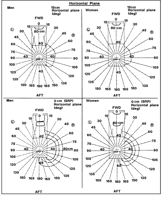
NASA-STD-3000 288b
Figure 3.3.3.3.1-1 Grasp Reach Limits With Right hand
for American Male and Female Populations (3 of 19)
NASA-STD-3000 288c
Figure 3.3.3.3.1-1 Grasp Reach Limits With Right hand
for American Male and Female Populations (4 of 19)
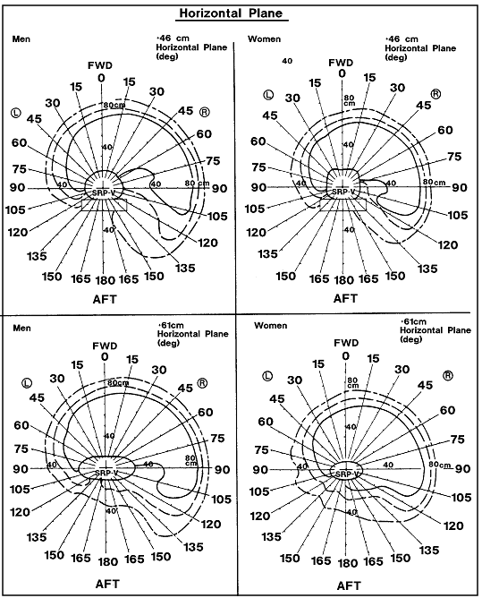
NASA-STD-3000 288d
Figure 3.3.3.3.1-1 Grasp Reach Limits With Right hand
for American Male and Female Populations (5 of 19)
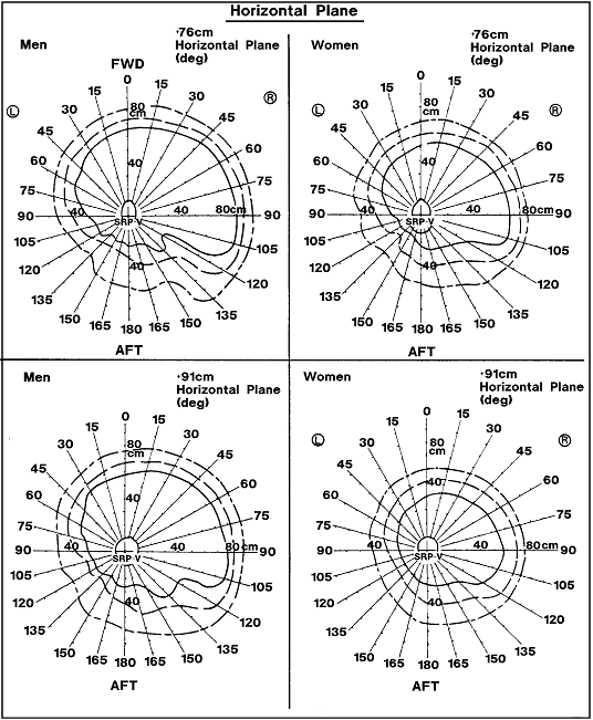
NASA-STD-3000 288e
Figure 3.3.3.3.1-1 Grasp Reach Limits With Right hand
for American Male and Female Populations (6 of 19)
NASA-STD-3000 288f
Figure 3.3.3.3.1-1 Grasp Reach Limits With Right hand
for American Male and Female Populations (7 of 19)
NASA-STD-3000 288g
Figure 3.3.3.3.1-1 Grasp Reach Limits With Right hand
for American Male and Female Populations (8 of 19)
| 
Notes:
a. Gravity conditions - the boundaries apply to 1-G
conditions only. Microgravity will cause the spine
to lengthen, and adjustments should be made based
on a new shoulder pivot location.
b. Subjects - the subjects used in this study are
representative of the 1967 Air Force population estimated
defined in Reference 16,
Chapter III. |
Reference:
310,
p. 35 to 52; NASA-STD-3000 288h
Figure 3.3.3.3.1-1 Grasp Reach Limits With Right hand
for American Male and Female Populations (9 of 19)
NASA-STD-3000 288i
Figure 3.3.3.3.1-1 Grasp Reach Limits With Right hand
for American Male and Female Populations (10 of 19)
NASA-STD-3000 288j
Figure 3.3.3.3.1-1 Grasp Reach Limits With Right hand
for American Male and Female Populations (11 of 19)
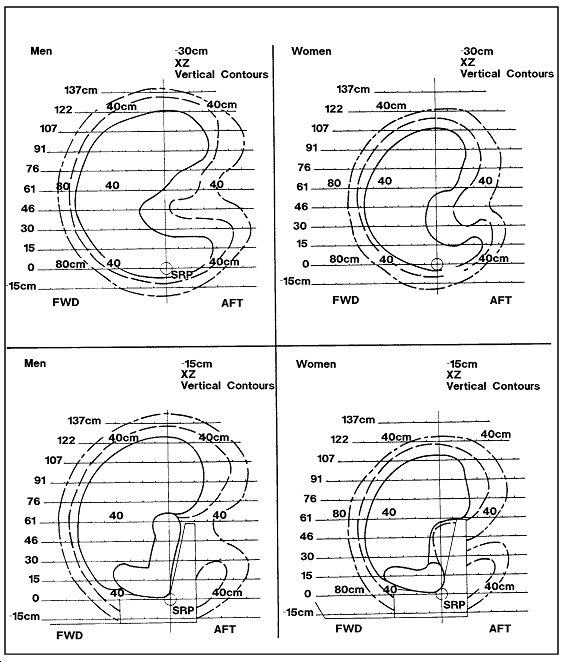
NASA-STD-3000 288k
Figure 3.3.3.3.1-1 Grasp Reach Limits With Right hand
for American Male and Female Populations (12 of 19)
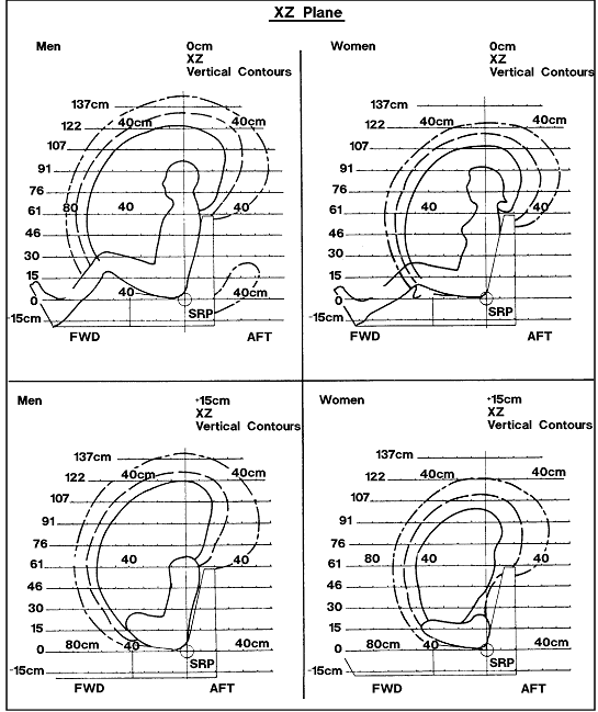
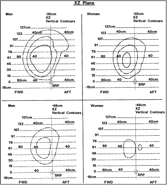
NASA-STD-3000 288l
Figure 3.3.3.3.1-1 Grasp Reach Limits With Right hand
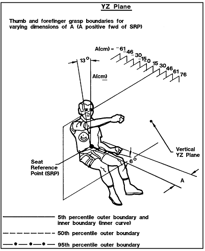
for American Male and Female Populations (13 of 19)
NASA-STD-3000 288m
Figure 3.3.3.3.1-1 Grasp Reach Limits With Right hand
for American Male and Female Populations (14 of 19)
NASA-STD-3000 288n
Figure 3.3.3.3.1-1 Grasp Reach Limits With Right hand
for American Male and Female Populations (15 of 19)
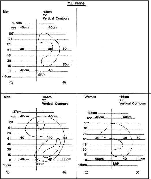
NASA-STD-3000 288o
Figure 3.3.3.3.1-1 Grasp Reach Limits With Right hand
for American Male and Female Populations (16 of 19)
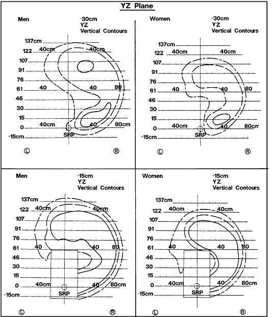
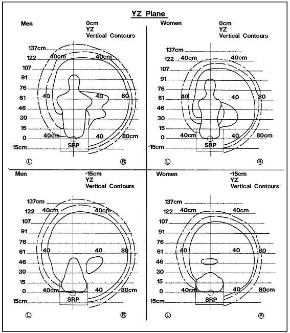
NASA-STD-3000 288p
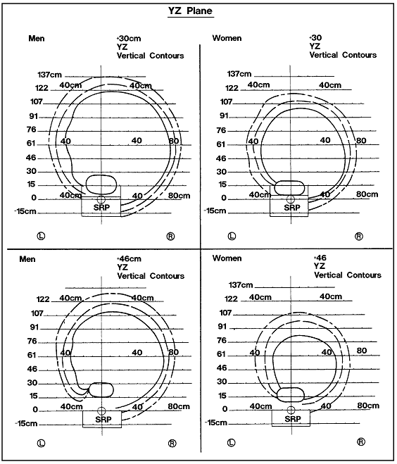
Figure 3.3.3.3.1-1 Grasp Reach Limits With Right hand
for American Male and Female Populations (17 of 19)
NASA-STD-3000 288q
Figure 3.3.3.3.1-1 Grasp Reach Limits With Right hand
for American Male and Female Populations (18 of 19)
NASA-STD-3000 288r
Figure 3.3.3.3.1-1 Grasp Reach Limits With Right hand
for American Male and Female Populations (19 of 19)
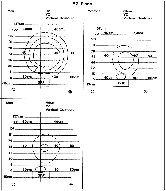
NASA-STD-3000 288s
Figure
3.3.3.3.1-2 Changes in Arm Reach Boundaries as a Function
of Variation in Backrest Angle of 13 Degrees From Vertical
| Direction Of Arm Reach
(Deg)
(From 0 deg or Straight Ahead, to 90 Deg To the Right) |
Approximate changes in
reach for each single degree of change in backrest
angle
(reach increases as backrest angle moves to vertical,
and vice versa) |
| 0 |
1.02 cm (0.40 in) |
| 15 |
1.27 cm (0.50 in) |
| 30 |
1.14 cm (0.45 in) |
| 45 |
0.94 cm (0.37 in) |
| 60 |
0.66 cm (0.26 in) |
| 75 |
0.36 cm (0.14 in) |
| 90 |
0.25 cm (0.10 in) |
Reference: 16,
Volume 1, p. V-61; NASA-STD-3000 287
b. Microgravity Handhold Restraint - Equipment and controls
operated in microgravity by crewmembers using a handhold
restraint, shall be within the functional reach boundaries
given in Figure 3.3.3.3.1-3.
The functional reach boundaries apply to tasks requiring
fingertip operation only. Adjustment for other grasp operations
shall be made in accordance with
Figure 3.3.3.3.1-5.
c. Microgravity Foot Restraint - Equipment and controls
operated in microgravity by crewmembers using a foot restraint,
shall be within the functional reach boundaries given in
Figures 3.3.3.3.1-4 and
3.3.3.3.1-5. The functional
reach boundaries apply to tasks requiring fingertip operation
only. Adjustment for grasp operations shall be made in accordance
with Figure 3.3.3.3.1-5.
Figure
3.3.3.3.1-3 Microgravity Handhold Restraint Reach Boundaries
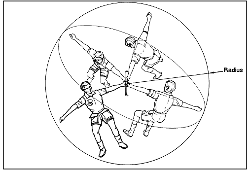
| |
Radius of fingertip reach boundary |
| 95th percentile male |
195 cm (77 inches) |
| 5th percentile female |
150 cm (63 inches) |
Notes:
a. Subjects - These data were generated using a computer-based
anthropometric model. The computer model was developed
using a sample of 192 male astronaut candidates and
22 female astronaut candidates measured in 1979 and
1980 (Reference 365).
The 5th percentile stature of the male population
is 167.9 cm (66.1 inches) and the 95th percentile
male stature is 189.0 cm (74.4 inches). The 5th percentile
stature of the female population is 157.6 cm (62.0
inches) and the 95th percentile female is 175.7 cm
(69.2 inches).
b. Gravity conditions - Although the motions apply
to a microgravity condition, the effects of spinal
lengthening have not been considered. |
Reference: 351;
NASA-STD-3000 337b
Figure
3.3.3.3.1-4 Microgravity Foot Restraint Reach Boundaries
- Fore/Aft
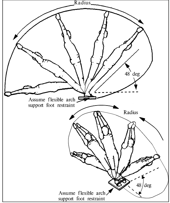
| Subject |
Radius Of
Reach Fingertip Boundary In X-Z Plane |
| Flexible arch support |
Fixed 'flat' foot restraint foot
restraint |
| 95th percentile Male |
222 cm (87 in) |
212 cm (83 in) |
| 5th percentile Female |
188 cm (74 in) |
172 cm (68 in) |
Notes:
a. Subjects - These data were generated using a computer-based
anthropometric model. The computer model was developed
using a sample of 192 male astronaut candidates measured
in 1979 and 1980 (Reference 365).
The 5th percentile stature of the male population
is 167.9 cm (68.1 inches) and the 95th percentile
male stature is 189.0 cm (74.4 inches). The 5th percentile
stature of the female population is 157.6 cm (62.0
in.) and the 95th percentile female is 175.7 cm (69.2
in).
b. Gravity conditions - Although the motions apply
to a microgravity condition, the effects of spinal
lengthening have not been considered.
c. Restraint configuration - two sets of dimensions
are given for the fore/aft reach boundary. One set,
the larger dimensions, apply to a fairly snug, but
flexible, arch support that allows the toes and heels
to raise slightly from the floor. The other set of
dimensions apply to a foot restraint that secures
the feet flat to the floor. |
Reference: 320;
NASA-STD-3000 337b
Figure
3.3.3.3.1-5 Microgravity Foot Restraint Reach Boundaries-Side
by Side (Using Flexible Arch Support Foot Restraint Configuration)
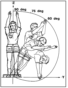
Notes:
a. The angle is measured between the x-axis and a
line drawn from the center of the foot restraint to
the foot restraint to the reach boundary.
b. The full reach boundary (up to 0 degrees angle)
will be provided in the next revision of this document.
c. These data were generated using a computer based
anthropometric model. The computer model was developed
using a sample of 192 male astronaut candidates and
22 female astronaut candidates measured in 1979 and
1980 (Reference 365).
The 5th percentile stature of the male population
is 167.9 cm (66.1 inches) and the 95th percentile
male stature is 189.0 cm (74.4 inches). The 5th percentile
stature of the female population is 157.6 cm (62.0
inches) and the 95th percentile female is 175.7 cm
(69.2 inches).
d. Although the motions apply to a microgravity condition,
the effects of a spinal lengthening have not been
considered.
Dimensions of fingertip reach boundary in YZ plane
| |
Angle
(degrees) |
Y-axis
dimension |
Z-axis
dimension |
| 95th
percentile male |
90 |
0 |
222 cm |
| 75 |
80 cm (31 in) |
193 cm (76 in) |
| 60 |
110 cm (43 in) |
160 cm (63 in) |
| 5th percentile
male |
90 |
0 |
188 cm (74 in) |
| 75 |
28 cm (11 in) |
175 com (69 in) |
| 60 |
80 cm (31 in) |
140 cm (55 in) |
| Reference: 320 |
Microgravity Foot Restraint Reach Boundaries-Side
by Side
| Type of task |
Adjustment |
| Finger tip operation |
+7.0 cm (2.8 in) |
| Full hand grasp |
-5.5 cm (2.2 in) |
| Reference: 310
|
|
Reference: 310,
p. 84; 320;
NASA-STD-3000 274
3.3.3.3.2
Strike Reach Envelope Data Design Requirements
{L}
If abrupt high accelerations are expected, items within
the strike envelope shall be designed to minimize injury
to the crewmember. Body strike envelopes as defined in
Figures 3.3.3.3.2-1 and
3.3.3.3.2-2 shall be used as appropriate
Figure
3.3.3.3.2-1 4-G Strike reach envelope of a Seated 95th
Percentile Male Wearing Full Restraint (Seat Belt and Dual
Shoulder Harness)
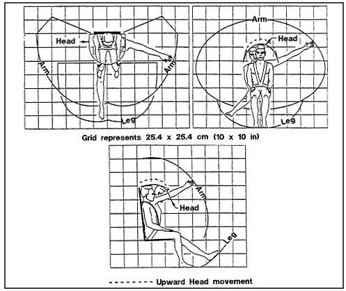
Notes: These figures show the envelope that the body
extremities (arms, legs, head, and torso) could strike
when the seated person is subjected to 4-G acceleration
either fore and aft or to the side (± Gx
or ± Gy). Refer to Paragraph
5.3.1, Introduction, for acceleration vector reference
conventions). |
Reference: 21,
DN3Q4, p. 3; NASA-STD-3000 334
Figure
3.3.3.3.2-2 4-G Strike reach envelope of a Seated 95th
Percentile Male - Lap Belt Only
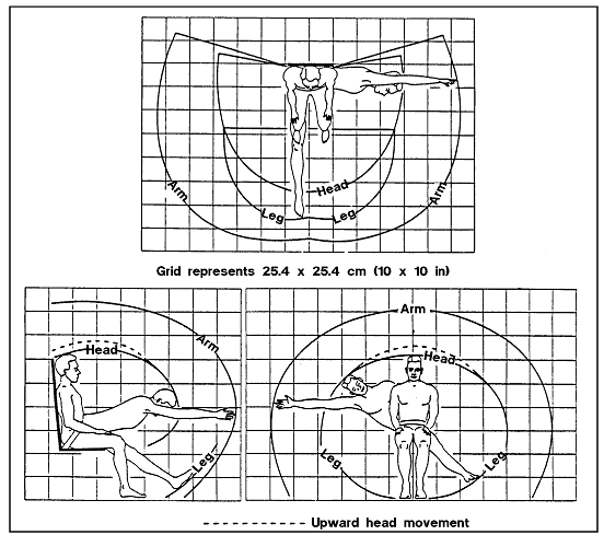
Notes: These figures show the envelope that the body
extremities (arms, legs, head, and torso) could strike
when the seated person is subjected to 4-G acceleration
either fore and aft or to the side (± Gx
or ± Gy). Refer to Paragraph
5.3.1, Introduction, for acceleration vector reference
conventions). |
Reference: 21,
DN3Q4, p. 3; NASA-STD-3000 335
(Refer to Paragraph 6.3.3,
Mechanical Hazards Design Requirements, for requirements
for protection from mechanical hazards).
{O}
{O}
This section describes the posture that the body assumes
in microgravity. Implications for habitat and crew station
design are given.
3.3.4.2
Neutral Body Posture Design Considerations
{O}
The crewmembers should not be expected to maintain a 1-G
posture in a microgravity environment. Having to maintain
some 1-G postures in microgravity may produce stress when
muscles are called on to supply forces that were normally
supplied by gravity. Stooping and bending are examples of
positions that cause fatigue in microgravity. In microgravity,
the body assumes a neutral body posture. The natural heights
and angles of the neutral body posture must be accommodated.
Some of the areas to be considered are as follows:
a. Foot Angle - Since the feet are tilted at approximately
111 degrees to a line through the torso, sloping rather
than flat shoes or restraint surfaces should be considered.
b. Feet and Leg Placement - foot restraints must be placed
under the work surface. The neutral body posture is not
vertical because hip/knee flexion displaces the torso backward,
away from the footprint. The feet and legs are positioned
somewhere between a location directly under the torso (as
in standing) and a point well out in front of the torso
(as in sitting).
c. Height - The height of the crewmember in microgravity
is between sitting and standing height. A microgravity work
surface must be higher than one designed for 1-G or partial-gravity
sitting tasks.
d. Arm and Shoulder Elevation - Elevation of the shoulder
girdle and arm flexion in the neutral body posture also
make elevation of the work surface desirable.
e. Head Tilt - In microgravity the head is angled forward
and down, a position that depresses the line of sight and
requires that displays be lowered.
(Refer to Paragraph 9.2.4,
Human/Workstation Configuration for additional information
on the design of microgravity workstations.
3.3.4.3
Neutral Body Posture Data Design Requirements
{A}
Space module crew stations shall be configured to accommodate
the neutral body posture shown in
Figure 3.3.4.3-1.
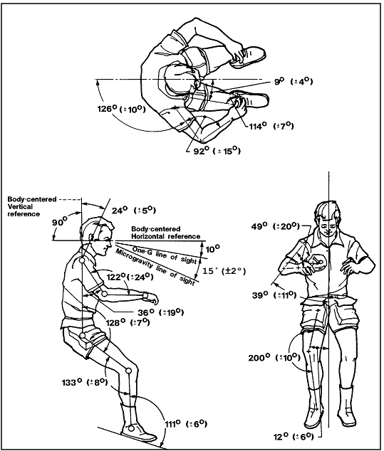
Note: The segment angles shown are means. Values
in parentheses are standard deviations about the mean.
The data was developed in Skylab studies and is based
on the measurement of 12 subjects. |
Reference: 7,
p. 24 to 26; 129,
Fig. 11; NASA-STD-3000 285
3.3.5 Body
Surface Area
{A}
{A}
This section provides a means of estimating the body skin
surface based on body mass and body stature.
(Refer to Paragraph 3.3.7.3.1.1,
Whole Body Mass Design Requirements for whole-body mass
data.)
(Refer to Paragraph 3.3.1,
Body Size Data Design Requirements, for stature data.)
3.3.5.2
Body Surface Area Design Considerations
{A}
The following are considerations for using the body surface
area estimations:
a. Gravity Environment - Body surface area estimation equations
apply to 1-G conditions only. They do not account for the
fluid shifts and spinal lengthening in microgravity.
(Refer to
Paragraph 3.2.3.1, Microgravity Effects Design Considerations,
for a discussion of corrections for microgravity conditions.)
b. Population - The equations given are most accurate for
the White or Black male and female body form. The equations
should not be used to estimate the body surface area of
the Asian Japanese female. Estimates for the body surface
area of the Japanese female will be provided in the next
revision of this document.
c. Application of Data - Body surface area data have several
space module design applications. These include:
1. Thermal control - Estimation of body heat production
for thermal environmental control.
2. Estimation of radiation dosage.
3.3.5.3
Body Surface Area Data Design Requirements
{A}
The body surface area data in
Figure 3.3.5.3-1 shall be used as appropriate to achieve
effective integration of the crew and space systems. These
data apply to 1-G conditions only.
Figure
3.3.5.3-1 Estimated Body Surface Area of the American
Male Crewmember
| American male
crewmember body surface area |
| 5th Percentile |
17,600 cm2 (2730 in
2) |
| 50th Percentile |
20,190 cm2 (3130 in2)
|
| 95th Percentile |
22,690 cm2 (3520 in2)
|
| Notes:
a. American male crewmember population is defined
in paragraph 3.2.1, Anthropometric
Database Design Considerations.
b. Data apply to 1-G conditions. |
Reference: 272,
p. 1; NASA-STD-3000 284
3.3.6 Body
Volume
{A}
{A}
The following section presents information on the volume
displaced by the body as a whole and the body segments.
3.3.6.2
Body Volume Data Design Considerations
{A}
The following are considerations for using body volume
data:
a. Gravity Environment - The data are based on 1-G conditions
and does not account for fluid shifts or spinal lengthening
due to weightlessness.
(Refer to
Paragraph 3.2.3.1, Microgravity Effects Design Considerations,
for a discussion of corrections for microgravity conditions.)
b. Population - The data provided in this paragraph apply
only to the White or Black male body form. The data should
not be used to estimate the body volume of the Asian Japanese
female. Estimates for the body volume of the Japanese female
will be provided in the next revision of this document.
3.3.6.3
Body Volume Data Design Requirements
{A}
The data in this section shall be used as appropriate to
achieve effective integration of the crew and space module.
Body volume data for the Japanese female crewmember cannot
be specified at this time due to insufficient data.
3.3.6.3.1 Whole-Body Volume Data Design Requirements
{A}
The whole-body volume data for the American male crewmember
in 1-G are given in Figure
3.3.6.3.1-1.
Figure
3.3.6.3.1-1 Whole Body Volume of American Male Crewmember
| American male
crewmember body volume |
| 5th Percentile |
68,640 cm3 (4190 in
3) |
| 50th Percentile |
85,310 cm3 (5210 in3)
|
| 95th Percentile |
101,840 cm3 (6210 in3)
|
| Notes:
a. These data apply to 1-G conditions only.
b. American male crewmember population is defined
in paragraph 3.2.1, Anthropometric
Database Design Considerations |
Reference: 276,
pp. 80, 81; NASA-STD-3000 283
3.3.6.3.2 Body Segment Volume Data Design Requirements
{A}
Body segment volume data for the American male crewmember
in 1-G are given in Figure
3.3.6.3.2-1.
Figure
3.3.6.3.2-1 Body Segments Volume of the American Male
Crewmember
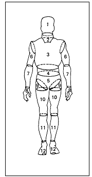
|
| Segment |
Volume, cm3
(in3) |
| |
5th percentile |
50th percentile |
95th percentile |
| 1 Head |
4260 (260) |
440 (270) |
4550 (280) |
| 2 Neck |
930 (60) |
1100 (70) |
1270 (80) |
| 3 Thorax |
20420 (1250) |
26110 (1590) |
31760 (1940) |
| 4 Abdomen |
2030 (120) |
2500 (150) |
2960 (180) |
| 5 Pelvis |
9420 (570) |
12300 (750) |
15150 (920) |
| 6 Upper arm * |
1600 (100) |
2500 (130) |
2500 (150) |
| 7 Forearm * |
1180 (70) |
1450 (90) |
1720 (100) |
| 8 Hand |
460 (30) |
530 (30) |
610 (40) |
| 9 Hip flap * |
2890 (180) |
3640 (220) |
4380 (270) |
| 10 Thigh minus flap * |
5480 (330) |
6700 (410) |
7920 (480) |
| 11 Calf * |
3320 (200) |
4040 (250) |
4760 (290) |
| 12 Foot * |
840 (50) |
1010 (60) |
1180 (70) |
| 5 + 4 + 3 Torso |
31870 (1940) |
40910 (2450) |
49870 (3040) |
| 9 + 10 Thigh * |
8360 (510) |
10340 (630) |
12300 (750) |
| 7 + 8 Forearm plus hand * |
1640 (100) |
1980 (120) |
2320 (140) |
| Notes:
*Average of right and left sides
a. These data apply to 1-G conditions only.
b. The American male crewmember population is defined
in paragraph 3.2.1, Anthropometric
Database Design Considerations. |
Reference: 276,
pp. 32-79; NASA-STD-3000 282T
3.3.7 Body Mass Properties
{A}
3.3.7.1 Introduction
{A}
This section discusses the mass of the human body and engineering
properties of the body mass. The following data are provided:
a. Body Mass - Both whole-body and body-segment mass data
are provided.
b. Center of Mass - Center of mass locations are defined
for both the whole body in defined positions and for body
segments.
c. Body Moment of Inertia - Moment of inertia data are
provided for the whole body in defined positions and for
body segments.
All data are based 1-G measurements.
3.3.7.2 Body Mass Properties Design Considerations
{A}
The following are considerations for using the body mass
properties data:
a. Effects of Microgravity on the Body - Microgravity causes
fluids to shift upward in the body and leave the legs. This
results in an upward shift of the center of mass for the
whole body and a loss of mass in the leg segments.
(Refer to
Paragraph 3.2.3.1, Microgravity Effects Design Considerations
for information to estimate the impact of microgravity on
the body mass data.)
b. Population - The only body mass data provided for the
Japanese female is whole body mass. Japanese female crewmember
center of mass and moment of inertia data cannot be specified
at this time due to insufficient data.
c. Body Weight Versus Body Mass - Although body mass remains
constant, body weight will depend on gravity conditions.
In 1-G body weight is calculated as indicated below:
1. Weight in lbs/32.2 = Mass in slugs
2. Weight in Newtons = mass in Kg X 9.8.
d. Application of Data - In microgravity, the body mass
properties define body reaction to outside forces. These
forces can be:
1. Reactive to forces exerted by the crewmember or a hand
tool.
2. Active forces from devices such as the Manned Maneuvering
Unit.
Both whole-body and body segment mass properties are given.
The reaction of the body to a force depends on both the
mass and the relative positions of the body segments. The
whole-body center of mass and moment of inertia data are
provided for 8 predefined positions. whole-body mass properties
for other positions would have to be determined by mathematically
combining the mass properties of the individual segments.
3.3.7.3 Body Mass Properties Data Design Requirements
{A}
The data in this section shall be used as appropriate to
achieve effective integration of the crew and space systems.
3.3.7.3.1 Body Mass Data Design Requirements
{A}
3.3.7.3.1.1
Whole-Body Mass Data Design Requirements
{A}
Whole-body mass data for the crewmember population in 1-G
are in Figure 3.3.7.3.1.1-1.
Figure
3.3.7.3.1.1-1 Whole body mass of year 2000 crewmember
population (age 40)
| Male (American) |
Female (Japanese) |
5th
percentile |
50th
percentile |
95th
percentile |
5th
percentile |
50th
percentile |
95th
percentile |
| 65.8 kg
(145.1 lb) |
82.2 kg
(181.3 lb) |
98.5 kg
(217.2 lb) |
41.0 kg
(90.4 lb) |
51.5 kg
(113.5 lb) |
61.7 kg
(136.0 lb) |
| Notes:
a. These data apply to 1-G conditions only. Fluid
losses in microgravity reduce these masses.
b. Year-2000 crewmember population is defined in
paragraph 3.2.1, Anthropometric
Database Design Considerations. |
Reference: 16,
308, pp. III-92,
III-85; NASA-STD-3000 281
3.3.7.3.1.2 Body Segment Mass Data Design Requirements
{A}
Body segment mass data for the American male crewmember
in 1-G are in Figure 3.3.7.3.1.2-1.
Figure
3.3.7.3.1.2-1 Mass of Body Segments for the American
Male Crewmember
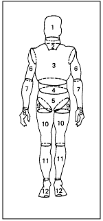
|
| Segment |
Mass, gm (oz, weight) |
| |
5th percentile |
50th percentile |
95th percentile |
| 1 Head |
4260 (150) |
440 (160) |
4550 (160) |
| 2 Neck |
930 (30) |
1100 (40) |
1270 (40) |
| 3 Thorax |
20420 (720) |
26110 (920) |
31760 (1120) |
| 4 Abdomen |
2030 (70) |
2500 (90) |
2960 (100) |
| 5 Pelvis |
9420 (330) |
12300 (430) |
15150 (530) |
| 6 Upper arm * |
1600 (60) |
2500 (70) |
2500 (90) |
| 7 Forearm * |
1180 (40) |
1450 (50) |
1720 (60) |
| 8 Hand |
460 (20) |
530 (20) |
610 (20) |
| 9 Hip flap * |
2890 (100) |
3640 (130) |
4380 (150) |
| 10 Thigh minus flap * |
5480 (190) |
6700 (240) |
7920 (280) |
| 11 Calf * |
3320 (120) |
4040 (140) |
4760 (170) |
| 12 Foot * |
840 (30) |
1010 (40) |
1180 (40) |
| 5 + 4 + 3 Torso |
31870 (1120) |
40910 (1440) |
49870 (1760) |
| 9 + 10 Thigh * |
8360 (290) |
10340 (360) |
12300 (430) |
| 7 + 8 Forearm plus hand * |
1640 (60) |
1980 (70) |
2320 (80) |
| Notes:
a. These data apply to 1-G conditions.
b. The American male crewmember population is defined
in paragraph 3.2.1, Anthropometric
Database Design Considerations Average of Right and
Left Sides |
Reference: 276,
pp. 32-79 With Updates; NASA-STD-3000 280
3.3.7.3.2 Center of Mass Data Design Requirements
{A}
3.3.7.3.2.1
Whole-Body Center of Mass Data Design Requirements
{A}
The whole body center of mass location data for the American
male crewmember in 1-G are in
Figure 3.3.7.3.2.1-1. Equations for locating the whole
body center of mass in males of different sizes, are given
in Figure 3.3.7.3.2.1-2.
Figure
3.3.7.3.2.1-1 Whole Body Center of Mass Location of
the American Male Crewmember
| .gif)
L(Y) - 1/2 distance between anterior
superior iliac spine landmarks (1/2 bispinous breadth). |
| Posture |
Dimension |
5th percentile |
50th percentile |
95th percentile |
| 1. Standing
.gif)
|
L(X) |
8.6 (3.4) |
9.1 (3.6) |
9.6 (3.8) |
| L(Y) |
11.7 (4.6) |
12.5 (4.9) |
13.3 (5.2) |
| L(Z) |
75.7 (29.8) |
80.2 (31.6) |
84.7 (33.3) |
2. Standing with arms over head
.gif)
|
L(X) |
8.7 (3.4) |
9.0 ((3.6) |
9.4 (3.7) |
| L(Y) |
11.7 (4.6) |
12.5 (4.9) |
13.3 (5.2) |
| L(Z) |
69.9 (27.5) |
73.9 (29.1) |
77.9 (30.7) |
| 3. Spread Eagle
.gif)
|
L(X) |
8.2 (3.2) |
8.6 (3.4) |
9.0 (3.6) |
| L(Y) |
11.7 (4.6) |
12.5 (4.9) |
13.3 (5.2) |
| L(Z) |
69.4 (27.3) |
73.5 (28.9) |
77.5 (30.5) |
| 4. Sitting
.gif)
|
L(X) |
19.4 (7.7) |
20.6 (8.1) |
21.8 (8.6) |
| L(Y) |
11.7 (4.6) |
12.5 (4.9) |
13.3 (5.2) |
| L(Z) |
65.2 (25.7) |
68.6 (27.0) |
71.9 (28.3) |
| 5. Sitting,
Forearms Down
.gif)
|
L(X) |
18.9 (7.4) |
20.0 (7.9) |
21.1 (8.3) |
| L(Y) |
11.7 (4.6) |
12.5 (4.9) |
13.3 (5.2) |
| L(Z) |
66.0 (26.0) |
69.3 (27.3) |
72.5 (28.6) |
6. Sitting, Thighs Elevated
.gif)
|
L(X) |
17.6 (6.9) |
18.8 (7.4) |
20.1 (7.9) |
| L(Y) |
11.7 (4.8) |
12.5 (4.9) |
13.3 (5.2) |
| L(Z) |
57.3 (22.5) |
59.4 (23.4) |
61.5 (24.2) |
| 7. Mercury Configuration
.gif)
|
L(X) |
19.4 (7.6) |
20.5 (8.1) |
21.5 (8.5) |
| L(Y) |
11.7 (4.6) |
12.5 (4.9) |
13.3 (5.2) |
| L(Z) |
66.8 (26.3) |
69.9 (27.5) |
73.0 (28.7) |
8. Relaxed (weightless)
.gif)
|
L(X) |
18.0 (7.1) |
18.8 (7.4) |
19.6 (7.7) |
| L(Y) |
11.7 (4.6) |
12.5 (4.9) |
13.3 (5.2) |
| L(Z) |
68.0 (26.8) |
70.9 (27.9) |
73.7 (29.0) |
| Notes:
a. These data apply to 1-G conditions. To estimate
center of mass location in microgravity, multiply
the L(z) figure by 0.9
b. The American male crewmember population is defined
in Paragraph 3.2.1, Anthropometric
Database Design Considerations |
Reference: 16,
Chapter IV, 250;
NASA-STD-3000
Figure
3.3.7.3.2.1-2 Whole Body Center of Mass Location for
American Male Crewmembers of Different Sizes
| Location of center of mass, cm = [ A
x (stature, cm) ] + [ B x (weight, lbs) ] + [C] |
| Posture |
Dimension |
A |
B |
C |
SE* (cm) |
R** |
| 1. Standing
.gif)
|
L (X) |
-0.035 |
0.024 |
11.008 |
0.33 |
0.7636 |
| L (Y) |
0 |
0.021 |
8.6 09 |
0.89 |
0.4310 |
| L (Z) |
0.486 |
-0.014 |
-4.775 |
1.33 |
0.9329 |
2. Standing (arms over head)
.gif)
|
L (X) |
-0.040 |
0.020 |
12.632 |
0.45 |
0.5823 |
| L (Y) |
0 |
0.021 |
8.609 |
0.89 |
0.4310 |
| L (Z) |
0.416 |
-0.007 |
0.305 |
1.52 |
0.8927 |
| 3. Spread eagle
.gif)
|
L (X) |
-0.031 |
0.020 |
10.443 |
0.36 |
0.6706 |
| L (Y) |
0 |
0.021 |
8.609 |
0.89 |
0.4310 |
| L (Z) |
0.392 |
0.002 |
2.547 |
1.48 |
0.8921 |
| 4. Sitting
.gif)
|
L (X) |
0.080 |
0.010 |
4.450 |
0.56 |
0.7900 |
| L (Y) |
0 |
0.021 |
8.609 |
0.89 |
0.4310 |
| L (Z) |
0.344 |
-0.004 |
7.327 |
1.46 |
0.8632 |
| 5. Sitting (thighs
elevated)
.gif)
|
L (X) |
0.041 |
0.022 |
7.405 |
0.66 |
0.7104 |
| L (Y) |
0 |
0.021 |
8.610 |
0.89 |
0.4310 |
| L (Z) |
0.212 |
-0.002 |
21.582 |
1.24 |
0.7801 |
| 6. Sitting (with
arms down)
.gif)
|
L (X) |
0.075 |
0.010 |
4.628 |
0.51 |
0.8030 |
| L (Y) |
0 |
0.021 |
8.609 |
0.89 |
0.4310 |
| L (Z) |
0.355 |
-0.010 |
7.389 |
1.56 |
0.8489 |
| 7. Mercury
configuration
.gif)
|
L (X) |
0.076 |
0.008 |
5.253 |
0.54 |
0.7828 |
| L (Y) |
0 |
0.021 |
8.609 |
0.89 |
0.4310 |
| L (Z) |
0.311 |
-0.002 |
14.425 |
1.80 |
0.7841 |
| 8. Weightless
.gif)
|
L (X) |
0.077 |
0.001 |
4.692 |
0.60 |
0.6973 |
| L (Y) |
0 |
0.021 |
8.609 |
0.89 |
0.4310 |
| L (Z) |
0.218 |
0.017 |
28.552 |
3.16 |
0.5015 |
| Notes:
a. These data apply to 1-G conditions only. To estimate
center of mass location in microgravity, multiply
the L(z) figure by 0.9.
b. The American male crewmember population is defined
in Paragraph 3.2.1, Anthropometric
Database Design Considerations. |
Reference: 250,
279; NASA-STD-3000
3.3.7.3.2.2 Body Segments Center of Mass Data Design Requirements
{A}
Center of mass of body location data for body segments
of the American male crewmember in 1-G are in
Figure 3.3.7.3.2.2-1
Figure
3.3.7.3.2.2-1 Body Segment of Mass for American Male
Crewmember
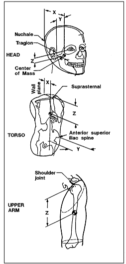 |
| Center of mass location, cm
(in) |
|
5th percentile |
50th percentile |
95th percentile |
| X |
Y |
Z |
X |
Y |
Z |
X |
Y |
Z |
| 9.4
(3.7) |
6.8
(2.7) |
2.1
(0.8) |
10.4
(4.1) |
7.2
(2.8) |
2.3
(0.9) |
11.5
(4.5) |
7.7
(3.) |
2.5
(1.0) |
| 8.4
(3.3( |
13.8
(5.4) |
21.0
(8.3) |
10.0
(3.9) |
15.8
(6.2) |
21.8
(8.6) |
11.6
(4.6) |
17.8
(7.0) |
22.6
(8.9( |
| * |
* |
14.1
(5.6) |
* |
* |
14.9
(5.9) |
* |
* |
15.7
(6.2) |
| Notes:
a. These data apply only to 1-G conditions.
b. The American male crewmember population is defined
in paragraph 3.2.1, Anthropometric
Database Design Considerations. |
Reference: 16,
Chapter IV; NASA-STD-3000 277a
Figure 3.3.7.3.2.2-1 Body Segment of Mass for American
Male Crewmember (Continued)
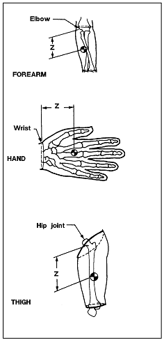 |
| Center of mass location,
cm (in) |
| 5th percentile
|
50th percentile
|
95th percentile
|
| X |
Y |
Z |
X |
Y |
Z |
X |
Y |
Z |
| * |
* |
10.9 (4.3) |
* |
* |
11.5 (4.5) |
* |
* |
12.1 (4.8) |
| * |
* |
5.1 (2.0) |
* |
* |
5.6 (2.2) |
* |
* |
6.0 (2.4) |
| * |
* |
17.0 (6.7) |
* |
* |
18.0 (7.1) |
* |
* |
19.1 (7.5) |
| Notes:
a. These data apply to 1-G conditions only.
b. The American male crewmember population is defined
in Paragraph 3.2.1, Anthropometric
Database Design Considerations Assume symmetry. |
Reference: 16,
Chapter IV; NASA-STD-3000 277b
3.3.7.3.3 Moment of Inertia Data Design Requirements
{A}
3.3.7.3.3.1 Whole-Body Moment of Inertia Data Design Requirements
{A}
Whole-body moments of inertia data for the American male
crewmember in 1-G are in
Figure 3.3.7.3.3.1-1.
Figure
3.3.7.3.3.1-1 Whole Body Moment of Inertia for the
American Male Crewmember
Moment of Inertia, g=cm2 x 106 (lb-in-sec2)
| Position |
Axis |
5th percentile |
50th percentile |
95th percentile |
| 1. Standing
.gif)
|
X |
106.5 (94.2) |
144.5 (101.3) |
182.3 (161.2) |
| Y |
94.9 (83.9) |
129.2 (114.3) |
163.4 (144.5) |
| Z |
10.3 (12.7) |
14.4 (12.7) |
18.5 (16.4) |
| 2. Standing,
Arms over head
.gif)
|
X |
141.0 (124.7) |
191.9 (169.7) |
242.6 (214.6) |
| Y |
124.6 (110.2) |
172.9 (152.9) |
221.0 (195.5) |
| Z |
10.6 (9.4) |
14.1 (12.5) |
17.5 (15.5) |
| 3. Spread Eagle
.gif)
|
X |
137.2 (121.3) |
190.4 (168.4) |
243.4 (215.3) |
| Y |
104.2 (92.2) |
144.8 (128.1) |
185.2 (163.8) |
| Z |
32.0 (28.3) |
46.6 (41.2) |
61.3 (54.2) |
| 4. Sitting
.gif)
|
X |
57.3 (50.7) |
76.9 (68.0) |
96.5 (85.3) |
| Y |
62.0 (54.8) |
83.2 (73.6) |
104.3 (92.2) |
| Z |
30.7 (27.2) |
42.4 (37.3) |
54.0 (47.8) |
| 5. Sitting, Forearms Down
.gif)
|
X |
59.2 (52.4) |
77.6 (68.6) |
96.0 (84.9) |
| Y |
63.9 (56.5) |
86.3 (76.3) |
108.6 (96.0) |
| Z |
30.9 (27.3) |
42.8 (37.9) |
54.6 (48.3) |
| 6. Sitting,
Thighs Elevated
.gif)
|
X |
37.6 (33.3) |
48.7 (43.1) |
59.8 (52.9) |
| Y |
37.2 (32.9) |
48.6 (41.2) |
55.8 (49.3) |
| Z |
23.9 (21.1) |
33.7 (29.8) |
43.5 (38.5) |
| 7. Mercury Configuration
.gif)
|
X |
62.5 (55.3) |
82.2 (72.7) |
101.8 (90.0) |
| Y |
69.6 (61.6) |
95.5 (84.5) |
121.3 (107.3) |
| Z |
31.9 (28.2) |
43.0 (38.0) |
54.0 (47.8) |
| 8. Relaxed (weightless)
.gif)
|
X |
88.0 (77.8) |
114.5 (101.3) |
140.9 (124.6) |
| Y |
84.1 (74.4) |
109.6 (96.9) |
134.8 (119.2) |
| Z |
39.8 (35.2) |
50.5 (44.7) |
61.2 (54.1) |
| Notes:
a. These data apply to 1-G condition only.
b. The American male crewmember population is defined
in Paragraph 3.2.1, Anthropometric
Database Design Considerations. |
Reference: 16,
IV-42,IV-25; NASA-STD-3000 276b
3.3.7.3.3.2 Body Segments Moment of Inertia Data Design
Requirement
{A}
Body segments moments of inertia data for the American
male crewmember in 1-G are in
Figure 3.3.7.3.3.2-1.
Figure
3.3.7.3.3.2-1 Body Segment Moment of Inertia for the
American Male Crewmember
Moment of inertia, g-cm2 x 103, (lb-in-sec2
x 103)
| Segment |
Axis |
5th percentile |
50th percentile |
95th percentile |
| Head
.gif)
|
X |
195.2 (172.7) |
207.1 (183.2) |
218.9 (193.6) |
| Y |
221.8 (196.2) |
236.8 (209.4) |
251.6 (222.6) |
| Z |
144.9 (128.1) |
152.2 (135.5) |
161.4 (142.7) |
| Neck
.gif)
|
X |
13.4 (11.9) |
18.2 (16.1) |
23.0 (20.3) |
| Y |
16.6 (14.7) |
22.0 (19.5) |
27.4 (24.2) |
| Z |
20.3 (17.9) |
27.5 (24.3) |
34.6 (30.6) |
| Thorax
.gif)
|
X |
3509.6 (3103.9) |
5312.0 (4697.9) |
7100.2 (6279.4) |
| Y |
2556.3 (2260.8) |
3920.6 (3467.4) |
5274.0 (4664.3) |
| Z |
2153.8 (1904.8) |
3320.1 (2936.3) |
4475.5 (3958.1) |
| Abdomen
.gif)
|
X |
116.6 (103.1) |
175.2 (155.0) |
233.2 (206.2) |
| Y |
63.3 (56.0) |
98.2 (86.8) |
132.6 (117.3) |
| Z |
173.6 (153.5) |
265.4 (234.7) |
356.1 (315.0) |
| Pelvis
.gif)
|
X |
713.7 (631.2) |
1123.4 (993.6) |
1528.9 (1352.1) |
| Y |
646.4 (571.7) |
1033.5 (914.0) |
1416.4 (1252.7) |
| Z |
820.0 (752.2) |
1303.6 (1152.9) |
1782.0 (1576.0) |
| Torso
.gif)
|
X |
10731.4 (9490.9) |
15957.8 (14113.0) |
21141.0 (18697.1) |
| Y |
2556.3 (2260.8) |
3920.6 (3467.4) |
5274.0 (4664.3) |
| Z |
2153.8 (19004.8) |
3320.1 (2936.3) |
5274.0 (4664.3) |
| Right upper
arm
.gif)
|
X |
92.6 (81.9) |
141.7 (125.4) |
190.5 (168.6) |
| Y |
97.6 (86.3) |
151.2 (133.7) |
204.4 (180.8) |
| Z |
18.5 (16.3) |
29.2 (25.8) |
39.8 (35.2) |
| Left upper
arm
.gif)
|
X |
89.1 (78.8) |
137.2 (121.43) |
185.0 (163.6) |
| Y |
93.3 (82.5) |
145.7 (128.9) |
197.8 (174.9) |
| Z |
17.8 (15.8) |
28.2 (24.9) |
38.4 (34.0) |
| Right forearm
.gif)
|
X |
65.3 (57.7) |
93.9 (83.1) |
122.4 (108.3) |
| Y |
66.3 (58.6) |
95.6 (84.6 |
124.8 (110.4) |
| Z |
9.6 (8.5) |
14.2 (12.6) |
18.8 (16.6) |
| Left forearm
.gif)
|
X |
63.7 (56.3) |
88.9 (78.6) |
113.9 (100.7) |
| Y |
66.4 (57.8) |
91.5 (80.9) |
117.4 (103.9) |
| Z |
8.9 (7.9) |
12.9 (11.4) |
16.9 (14.9) |
| Right hand
.gif)
|
X |
10.7 (9.4) |
13.8 (12.2) |
16.8 (14.9) |
| Y |
8.7 (7.7) |
11.2 (9.9) |
13.7 12.1) |
| Z |
3.4 (3.0) |
4.5 (4.0) |
5.5 (4.9) |
| Left hand
.gif)
|
X |
10.8 (9.5) |
13.6 (12.0) |
16.4 (14.5) |
| Y |
9.0 (7.9) |
11.3 (10.0) |
13.6 (12.0) |
| Z |
3.5 (3.1) |
4.4 (3.9) |
5.3 (4.7) |
| Right hip
flap
.gif)
|
X |
88.8 (78.5) |
134.1 (118.6) |
178.9 (158.2) |
| Y |
116.3 (102.8) |
173.1 (153.1) |
229.4 (202.9) |
| Z |
150.4 (133.1) |
226.5 (200.3) |
301.7 (266.9) |
| Left hip
flap
.gif)
|
X |
85.0 (75.1) |
128.8 (133.9) |
172.2 (152.3) |
| Y |
113.4 (100.3) |
169.2 (149.7) |
224.5 (198.5) |
| Z |
146.7 (129.8) |
219.2 (193.8) |
290.8 (257.2) |
| Right thigh minus flap
.gif)
|
X |
453.6 (401.2) |
653.1 (577.6) |
852.3 (753.8) |
| Y |
469.2 (415.0) |
673.4 (595.6) |
877.3 (775.9) |
| Z |
178.4 (157.8) |
255.2 (225.7) |
331.3 (293.0) |
| Left thigh minus
flap
.gif)
|
X |
437.3 (386.8) |
620.9 (549.1) |
804.0 (711.1) |
| Y |
460.7 (407.5) |
653.4 (577.9) |
845.7 (747.9) |
| Z |
172.3 (152.4) |
246.9 (218.3) |
321.0 (283.8) |
| Right calf
.gif)
|
X |
430.7 (381.0) |
618.1 (546.6) |
804.8 (711.8) |
| Y |
437.7 (387.1) |
627.1 (554.6) |
816.0 (721.7) |
| Z |
51.8 (45.8) |
72.0 (63.7) |
92.1 (81.5) |
| Left calf
.gif)
|
X |
434.1 (383.9) |
629.6 (556.8) |
824.7 (729.4) |
| Y |
441.4 (390.3) |
639.7 (565.8) |
837.7 (740.9) |
| Z |
50.7 (44.9) |
72.8 (64.4) |
94.7 (83.7) |
| Right foot
.gif)
|
X |
6.5 (5.7) |
8.7 (7.7) |
10.9 (9.6) |
| Y |
33.8 (29.9) |
46.1 (40.7) |
58.3 (51.5) |
| Z |
36.0 (31.8) |
48.8 (43.2) |
61.7 (54.5) |
| Left foot
.gif)
|
X |
6.1 (5.4) |
8.3 (7.4) |
10.6 (9.3) |
| Y |
32.4 (28.6) |
44.7 (39.5) |
57.0 (50.4) |
| Z |
34.2 (30.2) |
47.0 (41.6) |
59.8 (52.9) |
| Right thigh
.gif)
|
X |
1163.7 (1029.2) |
1689.8 (1494.4) |
2213.9 (1958.0) |
| Y |
1225.4 (1083.8) |
1780.9 (1575.0) |
2334.2 (2064.4) |
| Z |
316.5 (279.9) |
464.6 (410.9) |
611.3 (540.6) |
| Left thigh
.gif)
|
X |
1122.6 (992.6) |
1623.0 (1435.4) |
2121.1 (1875.9) |
| Y |
1186.3 (1049.2) |
1713.2 (1515.1) |
2237.5 (1978.8) |
| Z |
306.2 (270.8) |
448.5 (396.6) |
589.5 (521.3) |
| Right forearm plus hand
.gif)
|
X |
238.5 (210.9) |
327.8 (289.9) |
416.7 (368.5) |
| Y |
237.5 ((210.0) |
326.5 (288.8) |
415.1 (367.2) |
| Z |
13.4 (11.9) |
19.2 (17.0) |
25.0 (22.1) |
| Left forearm
plus hand
.gif)
|
X |
234.1 (207.0) |
314.1 (277.8) |
293.8 (348.3) |
| Y |
232.8 (205.9) |
312.2 (276.1) |
391.2 (346.0) |
| Z |
12.8 (11.4) |
17.9 (15.9) |
23.0 (20.3) |
| Notes:
a. These data apply to 1-G conditions only.
b. The American male crewmember population is defined
in Paragraph 3.2.1, Anthropometric
Database Design Considerations. |
Reference: 276,
pp. 32-79; NASA-STD-3000 275e
Return to Volume I Home


.gif)
.gif)
.gif)
.gif)
.gif)
.gif)
.gif)
.gif)
.gif)
.gif)
.gif)
.gif)
.gif)
.gif)


.gif)
.gif)
.gif)
.gif)
.gif)
.gif)
.gif)
.gif)
.gif)


.gif)
.gif)
.gif)
.gif)
.gif)
.gif)
.gif)
.gif)
.gif)
.gif)
.gif)
.gif)
.gif)
.gif)
.gif)
.gif)
.gif)
.gif)
.gif)
.gif)
.gif)
.gif)
.gif)
.gif)
.gif)
.gif)
.gif)
.gif)
.gif)
.gif)
.gif)
.gif)