Volume I, Section 14
14 EXTRAVEHICULAR ACTIVITY (EVA)
{A} For a description of the notations, see Acceleration
Regimes.
This section contains the following topics:
14.1 General EVA Information
14.2 EVA Physiology
14.3 EVA Anthropometry
14.4 EVA Workstations and Restraints
14.5 EVA Mobility and Translation
14.6 EVA Tools, Fasteners, and Connectors
14.7 EVA Enhancement Systems
See the video
clips associated with this section.
14.1 GENERAL EVA INFORMATION
{A}
14.1.1 General EVA Information Introduction
{A}
This section establishes guidelines for Extravehicular Activity (EVA). EVA is any activity performed by a pressure-suited crewmember in unpressurized or space environments. EVA begins with depressurization of the airlock or space module, and ends with repressurization of the space module or airlock after crewmember ingress. This includes any internal activities where a pressure-suited crewmember may be operating in normal modes of operation (e.g., airlocks, passageways, unpressurized work areas, donning/doffing areas) and abnormal modes of operation (e.g., unpressurized modules).
14.1.2 General EVA Design Considerations
{A}
EVA can provide an effective means for service, maintenance, repair, or replacement of space equipment without the need to remove it to a pressurized environment, return it to Earth or abandon it.
a. Classes - There are two basic classes of EVA:
1. Planned EVA - Conducted to accomplish tasks included in the nominally scheduled timeline to support selected mission operations.
2. Unplanned EVA - Conducted to accomplish tasks not included in the nominally scheduled timeline, but which may be required to achieve mission success, mission enhancement, or to repair or override failed systems.
In addition to the two basic classes of EVA, there are two other important characteristics of EVA tasks that are used to define design criteria and training requirements: criticality and complexity.
b. Criticality - An EVA task may be placed in one of three criticality categories:
1. Mission Enhancement - These are tasks that result in increased achievement of mission objectives. Usually tasks that get backed
2. Mission Success - Tasks that are required to achieve mission objectives.
3. Safety Critical - Tasks that must be accomplished to ensure the safety of the space module or the crewmembers.
c. Complexity - An EVA task may be classified in one of the three difficulty categories:
1. Simple EVA Tasks - that require use of standard tools, restraints, or mobility aids, and do not expose crewmembers to unique hazards.
2. Intermediate or Specialized EVA Tasks - Tasks that require additional tools or equipment, but are still procedurally simple.
3. Complex EVA Tasks - Tasks that require a significant extension of capabilities such as use of specialized tools, pose access (or restraint) problems, or require extended duration or unrestrained translation such as with a propulsion maneuvering unit.
d. Examples - Uses of EVA may include the following operations:
1. Support - Assembly, deployment, positioning, and mating/demating of large space structures.
2. Maintenance - Preventive and corrective maintenance such as Optical Surface Cleaning equipment positioning, inspection and replacement of equipment modules, activate/deactivate experiments, retrieve samples, resupply propellant or fluids, connect and disconnect utilities, and repair meteoroid or other damage.
3. Transfer - Transfer of cargo, equipment, and personnel, including the transfer of disabled crewmembers.
In a microgravity or reduced-gravity space environment, EVA crewmember capabilities relative to Earth-based, shirt- sleeve capabilities are improved for certain functions and degraded for others. The advantages of the microgravity environment allow the crewmember additional latitude during worksite operations, translation, and equipment transfer. The main factors that may degrade crewmember performance are pressure suit encumbrance, insufficient working volume, in- adequate crewmember restraint, and poor task or tool design.
There are no constraints imposed by sunlight/dark cycles, given proper considerations of space module/Sun angles and artificial illumination.
Space module equipment sensitive to EVA effluent discharge or particulate contamination should provide inherent self-protected features, or define EVA crewmember operational constraints.
14.1.2.1 EVA Compared to IVA and Alternative Approaches
{A}
14.1.2.1.1 Applications of EVA
{A}
The applications of EVA include:
a. Payload or mechanical override.
b. Maintenance and repositioning.
c. Extravehicular experimentation.
d. Payload, equipment, and personnel transfer.
e. Large space or planetary surface construction.
f. Satellite deployment and retrieval.
g. Servicing and repair.
h. Inspection.
14.1.2.1.2 Advantages of EVA
{A}
The advantages of EVA include:
a. Task flexibility at the worksite: the EVA crewmember can perform a very wide range of tasks.
b. Dexterous manipulation and one-handed or two-handed manipulation at the task site.
c. High-resolution visual interpretation of the task site.
d. Human cognitive and interpretive capability at the task site.
e. Decision-maker and effector are at the tasksite.
f. Crewmember at tasksite is capable of implementing real-time alternative and unique approaches to a problem.
14.1.2.1.3 Limitations of EVA
{A}
The limitations of EVA include:
a. Sensory degradation.
b. Limited duration.
c. Limited crewmember mobility and dexterity, force application, and endurance.
d. Operations time and resource overhead requirements.
e. Working volume and access limitations.
f. Hazards to the EVA crewmember.
14.1.2.1.4 Alternative Approaches to EVA
{A}
Sophisticated machine systems may relieve the EVA crewmember of routine and hazardous tasks as the technology for automation, teleoperation, and robotics evolves. Applications of robotics and teleoperation should be designed to achieve an optimum mix of human and machine resources, and substitute control as safety, productivity, and cost effectiveness warrant. Systems that employ machine applications should not be designed to preclude the use of EVA as backup.
The successful employment of alternatives to EVA is strongly dependent upon a foreknowledge of the worksite and tasks to be performed. For new and complex situations, EVA will remain the method of choice.
14.1.3 General EVA Safety Design Requirements
{A}
EVA crew safety shall be the paramount consideration in all EVA tasks.
The following EVA safety requirements are a compilation of general design features that shall be included in systems to ensure the safety of the crew and space module equipment.
(Refer to Section 6.0, Crew Safety, for additional safety requirements that pertain to EVA. In the event of conflict concerning EVA safety issues,
this section shall take precedence.)
The following safety requirements shall be followed to ensure the safety of the EVA crewmembers:
a. Temperatures - Surface temperatures of space module components requiring EVA interface shall be compatible with the touch-temperature limits of the pressure suit design being used.
b. Radiation - The EVA system design and operational procedures shall protect the EVA crewmember from radiation for the duration of the EVA exposure during the mission.
c. Micrometeoroids and Debris - EVA system design shall protect the EVA crewmember from expected particles including sand and dust.
d. Chemical Contamination - The EVA system shall protect the crewmember from hazardous chemical contamination.
e. Edges and Protrusions - All space module equipment and structures requiring an EVA interface must either be designed to preclude sharp edges or protrusions, or must be covered to protect the crewmember and the crewmember's critical support equipment.
f. Hazardous Equipment - Potentially hazardous items that could injure EVA crewmembers or damage EVA equipment by entrapment, snagging, tearing, puncturing, cutting, burning, or abrading shall be designed to ensure elimination of, or protection from, the hazard.
g. Ingress/Egress - EVA crewmembers shall always have a positive method and means to return to the pressurized module.
h. Power Sources - Special shielding and/or procedures shall be provided to preclude EVA approaches to a nuclear rector or radioisotopic generator power source located in the space module, that may result in additional radiation exposure.
i. Transmitters - Procedures shall be developed to protect crewmembers during EVA approaches that may result in harmful exposures to the non-ionizing radiation being emitted from all high-power electromagnetic EM wave transmitters (microwave, radar, laser, radio, UV/IR visible lamps) on or in the space module with exterior antennas or external apertures.
j. Tethers - EVA crewmembers shall be safety tethered to the space module at all times in microgravity, unless they are in a free-flying maneuvering unit or otherwise suitably restrained.
(Refer to Paragraph 14.4, EVA Workstations and Restraints, and
Paragraph 11.7.2, Personnel Restraints, for other restraint design considerations and requirements).
k. Ignition Sources - Electrical current limiting devices shall be provided to eliminate all potential ignition sources within any oxygen-enriched atmosphere of the life support system and pressure suit.
l. Positive Pressure - Protection shall be provided to prevent rupture by overpressurization of the crewmember's pressure envelop due to failure of the pressure supply system.
m. Electrical Voltage - The EVA crewmember shall be protected against electric voltage shocks from inadvertent grounding of electric circuits and from electrical discharge resulting from static charge buildup.
14.1.4 Space Suit Electrical Hazards Reduction Design Example
{A}
The maximum electrical current allowed within the oxygen-enriched environment of the Apollo space suits, through the Shuttle EMU space suit design, was 0.5 amps at the maximum ground level operating pressure of 140 kPa (20 psia). Current limiting devices are required to be used in flight EVA systems and interfacing ground support equipment to eliminate electrical hazards. Test methods and data pertaining to this are described in NASA JSC STD 8080, number 130, and in CSD-A-518, Study of the Apollo Spacesuit Electrical Fire Hazard.
14.2 EVA PHYSIOLOGY
{A}
14.2.1 Introduction
{A}
This section establishes guidelines for maintaining the EVA crewmembers' physiological well-being. It includes information that must be considered when designing EVA systems and planning EVA tasks. Topics covered are eye/hand coordination, tactile limits, reaction time, strength capabilities, workload, food and drinking water, body waste management, medical monitoring, and atmospheric conditions.
14.2.2 EVA Physiological Design Considerations
{A}
This section includes physiological design considerations in support of EVA.
14.2.2.1 EVA Vision Design Considerations
{A}
EVA vision is affected by variation in atmospheric attenuation, transmission of light through the helmet and visors, and visual display requirements.
(Refer to Paragraph 4.2.2, Vision Design Considerations for other considerations that pertain to vision.)
14.2.2.2 EVA Eye/Hand Coordination Design Considerations
{A}
Eye/hand coordination for the suited EVA crewmember is modified by the limits of the particular pressure suit.
(Refer to Paragraph 4.8, Coordination, for considerations that pertain to eye/hand coordination).
14.2.2.3 EVA Reaction Time Design Considerations
{A}
Sensory perception and reaction time are altered as a function of the stimuli in the space environment and the pressure suit encumbrances.
(Refer to Paragraph 4.7, Reaction Time, for considerations that pertain to general reaction time.)
14.2.2.4 EVA Strength-Related Design Considerations
{A}
The strength capabilities of the EVA crewmember are influenced by the pressure suit design as it affects body positions, as well as the positioning and restraint of the crewmember at the worksite location.
Strength data should be used as guidelines only, indicating trends and orders of magnitude of human force output. It should not be construed as valid for all groups. Muscle strength is situation-specific; it varies within the same person according to body position. Presently there is no single strength test in one position in which strength in other positions can be predicted. It is important to verify through simulations that the full range of potential EVA crews can perform the physical tasks required by the hardware design.
(Refer to Paragraph 4.9, Strength, for other considerations pertaining to strength).
14.2.2.5 EVA Workload Design Considerations
{A}
To minimize crew workload and maximize crew efficiency, planned EVAs should be conducted from a predetermined position by a restrained crewmember. In addition, training and task familiarization will also reduce workload.
(Refer to Paragraph 4.10, Workload, for other design considerations that pertain to workload).
14.2.2.6 EVA Food and Drinking Water Design Considerations
{A}
Sufficient food and drink for the total EVA duration should be provided for each EVA crewmember for all operations.
(Refer to Paragraph 7.2.2.2, Nutrition Design Considerations, and to
Paragraph 10.5.2, Galley and Wardroom Design Considerations, for other considerations that pertain to nutrition, food, and water).
14.2.2.7 EVA Body Waste Management Design Considerations
{A}
The EVA waste management system should be user-acceptable, comfortable, and safe to use, without being attended, for the EVA duration.
Assuming that, through diet control and health maintenance, defecation is unlikely to occur while wearing the in-suit body waste management system, the system should accommodate urine for men, urine and menses for women, and should provide containment of defecation resulting from an episode of diarrhea.
The system should take a minimum amount of pre- and post-use stowage volume and servicing time.
During EVA, vomitus protection should be provided to protect the crewmember and keep the airway passage open, being unconstraining to the crewmember during normal EVA.
(Refer to Paragraph 10.3.2, Body Waste Management Facilities Design Considerations, for other considerations that pertain to body waste management).
14.2.2.8 EVA Medical Monitoring Design Considerations
{A}
EVA medical monitoring systems should be comfortable to the crewmember and not interfere with any EVA operations.
14.2.2.9 EVA Suit Pressure Design Considerations
{A}
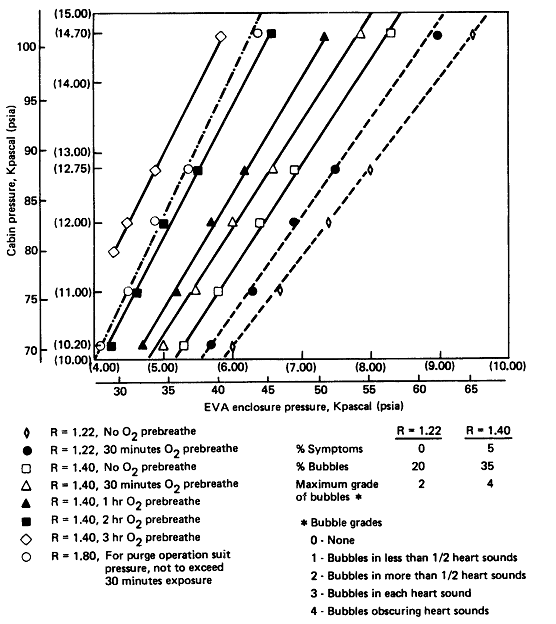
An increased EVA suit pressure has the benefit of reducing or eliminating the prebreathe time required to denitrogenate the body to preclude the bends, and of giving ample margin between operating pressure and minimum emergency pressure.
A decreased suit pressure has the demonstrated benefit of reducing space suit operating forces, pressure loads, and structural bulk. In any given soft space suit design, lower pressure results in increased mobility.
Optimal cabin and suit pressure combinations should allow zero-prebreathe EVAs, preclude decompression sickness and effect minimal subsymptomatic bubble formation.
Figure 14.2.2.9-1 presents several cabin-and suit -pressure combinations with an R value is the ratio of tissue nitrogen partial pressure to the final total pressure). Alternate pressures with a 30-minute pure oxygen prebreathe are also given. A higher R value of 1.4 is medically acceptable, but may result in a low incidence of decompression sickness.
R values above 1.4 should not be considered for nominal operations.
A suit pressure with an R value of 1.8 is acceptable for contingency purge flow operations of no longer than 30 minute duration. Contingency purge systems should provide 100% oxygen.
Figure
14.2.2.9-1 Possible Space Module Pressures Versus EVA Enclosure
Pressure
| Textual Representation |
| R = 1.22, No O2 prebreathe |
| R = 1.22, 30 minutes O2
prebreathe
|
| R = 1.40, No O2 prebreathe
|
| R = 1.40, 30 minutes O2
prebreathe |
| R = 1.40, 1 hr O2 prebreathe |
| R = 1.40, 2 hr O2 prebreathe |
| R = 1.40, 3 hr O2 prebreathe |
| R = 1.80, For purge operation suit
pressure, not to exceed 30 minutes exposure |
|
R = 1.22 |
R = 1.40 |
| % Symptoms |
0 |
5 |
| % Bubbles |
20 |
35 |
| Maximum grade of bubbles* |
2 |
4 |
| 0 - None |
| 1 - Bubbles in less than 1/2 heart sounds |
| 2- Bubbles in more than 1/2 heart sounds |
| 3 - Bubbles in each heart sound |
| 4 - Bubbles obscuring heart sounds |
|
Reference: 264, Figure 11.1; NASA-STD-3000 298
14.2.2.10 EVA Radiation Dosage Design Considerations
{A}
(Refer to Paragraph 5.7, Radiation, for other design considerations related to radiation exposure and protection design considerations).
a. Radiation Exposure Limits - Allowable limits for EVA radiation doses will depend on the radiation exposure limits set for the entire mission and the doses acquired during IVA (based preferably on active dosimetry measurements or measurements combined with the shielding capability of the space module). The maximum permissible EVA radiation exposure will be the difference between the mission limits and the IVA doses. A margin of safety should be included to accommodate unexpected radiation exposures during EVA.
b. Space Suit Radiation Protection - The space suit design, including visors, should be based on the conditions of the local radiation environment.
c. UV Light - The materials used for the space suit helmet and visors should provide adequate UV absorption characteristics to provide protection against direct and reflected UV light from the Sun. Protection against UV light should also be considered in EVAs that bring crewmembers near large solid-angle surfaces with high reflectivity in the UV range.
d. Solar Flares - Real-time monitoring and notification about solar activities will be necessary for regions of space where solar event radiation can reach the EVA crewmember because the onset of large solar flares may require aborting the EVA.
e. Polar Orbits - Auroral electron charging effects should be considered in the design of EVA systems when Polar orbit EVA operations are performed.
14.2.2.11 EVA Touch Temperature Considerations
{A}
Temperatures of items the crewmember will come in contact with during EVA will vary more widely than those acceptable for IVA.
Acceptable touch temperature is a function of the suit design configuration being used, contact pressure, heat transfer characteristics of the object, and duration.
Materials degradation caused by temperature extremes should be considered in establishing touch temperature requirements.
(Refer to Paragraph 6.5.2, Touch Temperature Design Considerations.)
14.2.3 EVA Physiological Design Requirements
{A}
This section includes design requirements for the physiological aspects of EVA.
14.2.3.1 EVA Vision Design Requirements
{A}
No requirements that apply only to EVA have been identified. Data pertaining to EVA requirements will be included in revisions to this document.
14.2.3.2 EVA Eye/hand Coordination Design Requirements
{A}
No requirements that apply only to EVA have been identified. Data pertaining to EVA requirements will be included in revisions to this document.
14.2.3.3 EVA Reaction Time Design Requirements
{A}
No requirements that apply only to EVA have been identified. Data pertaining to EVA requirements will be included in revisions to this document.
14.2.3.4 EVA Strength-Related Design Requirements
{A}
Design forces required for operation of hardware shall not exceed the capabilities of the potential population of EVA crewmembers within a given pressure suit design.
(Refer to Paragraph 4.9.3, Strength Design Requirements, for requirements that pertain to nude-body strength in 1-G.)
14.2.3.5 EVA Metabolic Workload Design Requirements
{OP}
The EMU shall be able to support a mean metabolic rate of 250 kcal/hr (1000 Btu/hr) for 60 minutes, and a sustained minimum level of 65 kcal/hr (250 Btu/hr).
14.2.3.6 EVA Food and Drinking Water Design Requirements
{OP}
Food and drinking water requirements are variable based on the frequency and length of scheduled EVAs:
a. Water requirements - Water shall be available during EVA at a rate 240 cc/hr (8 oz/hr) for EVA over 3 hours.
b. Food Requirements are as follows:
1. EVAs of 4 hours or less in duration may be managed with 200 kcal (795 Btu) of food.
2.EVAs of greater than 4 hours apart may be managed with 200 kcal (795 Btu) of food.
3. Single or multiple EVAs of 4 to 8 hours in aggregate and repeated at intervals less than 48 hours apart may be managed with 750 kcal (2975 Btu) of food.
c. Materials used shall meet the current FDA requirements that pertain to food and drinking water.
(Refer to Paragraph 7.2.2.3, Nutrition Design Requirements for data relative to portable water compatibility.)
14.2.3.7 EVA Body Waste Management Design Requirements
{A}
The EVA in-suit body waste management system shall provide for the collection and disposal of human wastes in an aesthetic and reliable manner that shall not degrade the crewmember performance. Specifically, the system design shall include the following:
a. Body Wastes to be Accommodated - accommodation o 1000 cc (33 oz) of urine for men and women, and menses for women.
b. Contamination Protection - prevention of odor, particles, biotic containers, and/or toxicants.
c. Duration of Accommodation - accommodation of body wastes for maximum suited duration.
d. Oral/Nasal Breathing Environment - Space suit systems in combination with EVA procedures shall provide for an in-helmet environment that provides protection from:
1. Defecation in the suit.
2. Vomiting in the suit.
3. Loose food or waste particles.
4. Free-floating liquids.
(Refer to Paragraph 10.3.3, Body Waste Management Facilities Design Requirements, for other information that pertains to body waste management.)
14.2.3.8 EVA Medical Monitoring Design Requirements
{A}
A real - time physiological monitoring capability shall be provided for each EVA crewmember to measure physiological parameters. The monitoring device shall provide:
a. Detection Capability - the capability to detect physiological stress and/or excess during EVA.
b. Mobility - minimally interfere with personnel mobility.
c. Checkout Time - require minimum checkout time.
d. Communications, Caution, and Warning - the capability for real-time downlink, as well as in-suit caution and warning alarms, and the provision of caution and warning alarms for intravehicular crewmember support..
(Refer to Paragraph 9.4.4.3, Caution and Warning System Design Requirements, for specific requirements.)
e. Monitor Parameters - parameters that shall be monitored include:
1. O2 consumption.
2. Heart rate and EKG signal.
3. Suit pressure.
4. In-suit partial pressure (for active two-gas life support systems designs).
5. CO2 pressure.
6. A physiological monitoring capability shall be provided for each EVA crewmember to measure radiation exposure in the suit either actively or passively depending on the radiation environment.
(Refer to paragraph 5.7.2.2.3, Ionizing Radiation Monitoring and Dosimetry Design Requirements, and
Paragraph 5.7.2.2.4, Ionizing Radiation Personnel Protective Equipment Design Requirements, for other applicable requirements. Refer to
Paragraph 6.4.3, Electrical Hazards Design Requirements, and Section 10.9, Space Medical Facilities, for information that pertains to EVA medical monitoring.)
14.2.3.9 EVA Suit Pressure Design Requirements
{A}
The following shall be required for EVA suit pressure design:
a. O2 Pressure - The O2 pressure in the space suit shall be maintained above the minimum normoxic levels shown in
Figure 14.2.3.9-1.
Figure 14.2.3.9-1
Normaxic O2 Pressure as a Function of Total Pressure
|
Total pressure
|
Normoxic O2 pressure
|
|---|
| p>Kpascal |
(psi)
|
kPa
|
(psi)
|
|
25.51
|
3.70
|
25.51
|
3.70
|
|
27.58
|
4.00
|
24.96
|
3.62
|
|
34.47
|
5.00
|
23.79
|
3.45
|
|
41.37
|
6.00
|
23.17
|
3.36
|
|
48.26
|
7.00
|
22.68
|
3.29
|
|
55.16
|
8.00
|
22.34
|
3.24
|
|
62.05
|
9.00
|
22.06
|
3.20
|
|
68.95
|
10.00
|
21.86
|
3.17
|
|
101.35
|
14.70
|
21.24
|
3.08
|
Reference: 264, Table 11.2; NASA-STD-3000 299
Figure 14.2.3.9-2
Exposure Limits to Partial Pressures During EVA Preparation
|
O2 partial pressure
|
Limitations
|
|---|
|
Range
|
Hours per period
|
|
Kpascal
|
(psi)
|
|
|
69 - 101
|
(10 - 14.7)
|
6 hours/24 hour period
18 hours/120 hour period
|
|
41 - 69
|
( 6 - 10.0)
|
18 hours/120 hour period
|
|
27 - 41
|
( 3 - 6.0)
|
None
|
Reference: 264, Table 11.2; NASA-STD-3000 300
b. O2 Partial Pressure Exposure - Exposure to O2 partial pressure during EVA preparation and during EVA shall be limited as a function of time due to O2 toxicity concern as shown in
Figure 14.2.3.9-2.
c. High O2 Partial Pressure Exposure - Chronic (>6 hrs) exposure to O2 partial pressure above 310 mmHg (6.0 psi) will require crew health assessment with pulmonary function tests and laboratory tests.
d. CO2 Partial Pressure Exposure - The inspired CO2 (CO2 in the gas stream directed to the helmet plus the CO2 rebreathed from respiration) shall not exceed 7.6 mmHg (0.15 psi) at metabolic rates up to 400 kcal/hr (1600 Btu/hr). The inspired CO2 shall not exceed 10 mmHg (0.19 psi) for periods up to 15 minutes at metabolic up to 500 kcal (2000 Btu/hr), and shall not exceed 15 mmHg (0.29 psi) for periods of 5 minutes
at metabolic rates up to 630 kcal/hr (2500 Btu/hr).
e. Rate of Pressure Change - The rate of pressure change experienced by the crew member during either normal depressurization or repressurization shall not exceed 2.6 mmHg/second (0.05 psi/second).
f. Rate of Emergency Repressurization - The rate of emergency repressurization shall not exceed 52 mmHg/second (1.0 psi/second) and shall not result in a crewmember peak differential pressure across the chest in excess of 80 mmHg (1.5 psi) or 40 mmHg (0.77 psi) for a period longer than 5 seconds.
14.2.3.10 EVA Radiation Dosage Design Requirements
{A}
(Refer to Paragraph 5.7.2.2, Ionizing Radiation Design Requirements, and
Paragraph 5.7.3.2, Non-Ionizing Radiation Design Requirements, for other radiation dosage design requirements.)
a. Radiation Protection - Sufficient protection to keep radiation exposure below permissible EVA limits based on the maximum predicted radiation levels and the maximum expected task durations.
b. EVA Radiation Exposure limits shall be based on NASA exposure limits:
1. Mission exposure limits shall be set.
2. Based on the mission exposure and the radiation dose acquired during IVA, permissible EVA radiation exposure limits shall be set.
c. Non-ionizing Radiation Standards:
1. Using terrestrial exposure standards for non-ionizing radiation as a basis, exposure standards for non-ionizing radiation shall be established.
2. These standards shall be applied to protect EVA crewmembers from possible contact with high levels of non-ionizing radiation being emitted by exterior antennas or apertures.
d. UV Eye Protection - the design of the space suit helmet and visors shall provide adequate eye protection to the EVA crewmember from the Sun's direct and reflected UV radiation for the duration of EVA exposure.
14.2.3.11 EVA Touch Temperature and Pressure Design Requirements
{A}
EVA touch temperatures and pressures are as follows:
a. EVA Space Suit - The Space Station Extras Vehicular Mobility Unit (SSEMU) shall maintain space suit internal surface temperatures between 10 degrees C (50 degrees F) and 43 degrees C (110 degrees F).
b. EVA Glove - The EVA glove shall provide the above protection during the subsequent to the period that the external surface of the glove is loaded to 52 mmHg (1-0 psi) for 0.5 minute by an object with a surface temperatures between -120 degrees C (-185 degrees F) and 113 degrees C (+235 degrees F).
(Refer to Paragraph 6.5.3, Touch Temperature Design Requirements, for other specific requirements.)
14.2.4 Example EVA Physiological Design Solutions
{OP}
This section includes example design solutions used during STS missions for some physiological aspects of EVA. It should be noted that some of the existing designs do not meet all of the requirements of this standard.
14.2.4.1 EVA Body Waste Management Example Design Solutions
{OP}
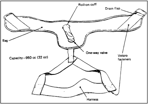
For Shuttle EVAs, the problem of body waste management is solved by collecting liquid wastes in a disposable urethane-coated nylon bag as shown in
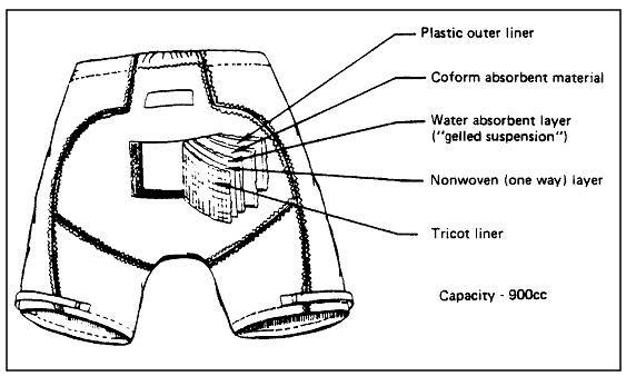
Figure 14.2.4.1-1, UCD-Urine Collection Device, and worn by male crewmembers under LCNG. Female crewmembers wear a disposable containment trunk, which collects liquid wastes in a super-absorbent material. This trunk is shown in
Figure 14.2.4.1-2, Disposable Absorption Containment Trunk (DACT).
Figure 14.2.4.1-1
Urine Collection Device (UCD) as an Example of a Body Waste Management
System for Males During EVA
Reference: 351, NASA-STD-3000 301
Figure 14.2.4.1-2
The Disposable Absorption Containment Trunk (DACT) as an Example of
a Body Waste management System for Females During EVA
Reference: 320; NASA-STD-3000 302
14.2.4.2 EVA Food and Drinking Water Example Design Solution
{OP}
For Shuttle EVAs, drinking water is obtained from the in suit drink bag IDB. The IDB is a urethane film bag RF heat sealed together in the shape of the volume available in the front of the HUT. The bag contains a valve that is activated by a sucking motion so the crewmember obtains a drink as if using a straw. The valve precludes spillage caused by pressing on the bag. The bag is attached by Velcro into the front of the HUT, so the drink tube is easily available.
A food stick is next to the IDB on the JUT. The food stick is an edible paper sheath that allows the crewmember to grip it with his/her teeth, pull it up, and take a bite. The IDB is shown in
Figure 14.2.4.2-1.
Figure 14.2.4.2-1
EVA In-suit Drink Bag as an Example of a Way to Provide Water to the
EVA Crewmember

Reference: 320; NASA-STD-3000 303
14.2.4.3 EVA Example Medical Monitoring Design Solutions
{A}
The STS EMU contains an Operational Bio-instrumentation System OBS that consists of three chest electrodes, a signal conditioner, and connecting cables. It provides an EKG signal during EVA.
14.2.4.4 EVA Radiation Dosage Example Design Solutions
{A}
In an attempt to reduce microwave radiation exposure during STS EVAs, a mission rule requires that nearby antennas be turned off during EVA.
14.2.4.5 EVA Glove Example Design Solutions
{A}
The STS EMU glove design maintains the crewmen's skin temperature between 10 and 38 degrees C (50 and 100 degrees F) when the external surface of the glove is loaded to 6.89 kp (1.0 psi for 0.5 minute by an object with a surface temperature between -118 and 113 degrees C(-180 and +235 degrees F).
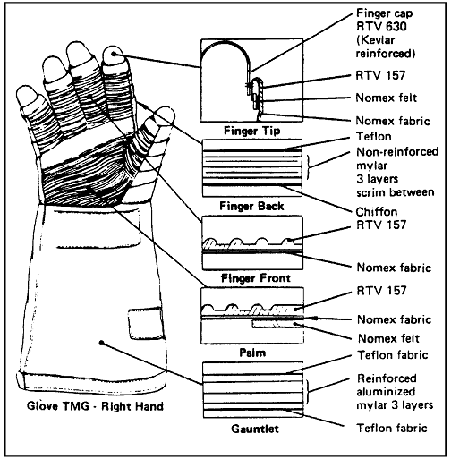
The Glove Thermal Micrometeoroid Garment TMG has a varying cross section to optimize hand mobility, abrasion resistance, and to provide thermal protection. The five different cross sectional areas are (1) Finger Tip, (2) Finger Back, (3) Finger Front, (4) Palm, and (5) Gauntlet. The Glove thermal garment is illustrated in
Figure 14.2.4.5-1.
Figure 14.2.4.5-1
Shuttle EVA Glove as a Touch Temperature Design Solution
Reference: 320; NASA-STD-3000 304
The Finger Tip lay-up has four different materials. These materials are shown in cross section in the adjacent figure. The RTV 157 is an outer coating used for abrasion resistance. The Nomex Fabric is a very strong, durable fabric that adheres to the RTV. The Nomex Felt is used primarily for thermal protection and secondly for abrasion protection. And, finally, the finger cap RTV 630 is used to enhance the crewmember's fingertip, tactility, while providing protection.
The Finger Back lay-up has four different materials. The Teflon provides abrasion and thermal protection, while the Mylar reflects the Sun's radiation. The scrim between each of the three layers of Mylar provides insulation the same way double-pane windows do. The chiffon material protects the Mylar from abrading against the glove restraint.
The Finger Front is coated with RTV 157 to enhance gripping and tactility, as well as provide the thermal resistance. Again, the Nomex fabric is used because of its excellent wear and adhesion properties.
The Palm cross section shows three materials. Again, the RTV 157 is used for abrasion resistance and tactility. The Nomex felt serves as thermal protection. The felt reduces the heat transfer across the TMG while also providing abrasion resistance against the glove restraint.
The final area of cross section analysis is the Gauntlet. The cross section has two materials. The reinforced Mylar serves the same purpose as in the Finger Back, but is reinforced for greater durability. The Teflon provides abrasion resistance and protection.
14.3 EVA Anthropometry
{A}
14.3.1 Introduction
{A}
The anthropometric design considerations and dimensions for EVA crewmembers are discussed in this section. These include joint motion, movement ranges, neutral body posture, head movement, viewing limits, and working envelopes as well as pressure suit dimensions and design considerations.
(Refer to Section 3.0, Anthropometry and Biomechanics, for size, reach, and mobility of the nude or lightly clothed crewmember).
14.3.2 EVA Anthropometric Design Considerations
{A}
The anthropometric ranges and the mobility restrictions imposed by any pressurized space suit must be considered during space systems design.
Basic anthropometric dimensions are normally given for nude or shirt sleeve conditions. In an EVA situation is altered due to the effective size of the crewmember pressure suits and life support equipment. Such clothing and equipment significantly affect the range of joint movement and influence the design layout of workspaces.
Anthropometric data that should be considered in hardware design include:
a. suited anthropometric data on the smallest female and the largest male EVA crewmember.
b. Human growth projections for the anticipated period through which the space suit will be in use.
(Refer to Paragraph 3.2, General Anthropometric and Biomechanics Related Design Considerations, for other considerations which pertain to anthropometrics.)
14.3.2.1 Space Suit Design Considerations and Dimensions
{A}
The space suit is a complete anthropomorphic system that provides pressure, ventilation, humidity and thermal control. and communication for the crewmember during EVA.
Design considerations and goals for the space suit should include:
a. Mobility - Space suit mobility that approaches that of the nude body ranges.
b. Sizing - Resizing capability among crewmembers should provided to minimize suit quantity and stowage volume required. Finger/thumb, arm, let, and torso length adjustment capabilities should be provided for individual crewmember mobility and comfort.
c. Environmental Protection - Space suit insulative lay-up provides environmental protection and effects bulk, volume and mobility ranges of the EMU.
d. Glove Dexterity - Space suit gloved hand dexterity that approaches that of bare-hand operations.
e. Dynamic Loading - Design load values of the structure of the pressure restraints and a consideration in space suit design. The pressurized components of the suit can adequately be modeled as thin shells under pressure to determine pressure loads. In the case of longitudinal or axial loads, the loads induced by the crewmember's interaction with the suit should be accounted for as they are often larger than the pressure loads. These loads are additive to the pressure loads that act in the axial direction. Crew induced loads on the suit depend on the suit architecture and the suit/crewmember fit. The stiffness of the axial loads distribution paths is the prime factor in making crewmember induced loads suit specific.
f. Controls and Displays - Suit mounted controls and displays should be selected and located in consideration of operational, visual, and volumetric constraints.
14.3.2.1.1 Space Suit Glove Design Considerations and Dimensions
{A}
Space suit gloves degrade tactile proficiency compared to bare hand operations. Dexterity can be compared to that of heavy work gloves, many standard handles, knobs, toggle switches and buttons can be operated with EVA gloves. Attention should be given to the design of manual interfaces to preclude or minimize hand fatigue or physical discomfort.
The space suit glove assemblies should be designed to allow the hand to function with a minimum of mobility restrictions, while satisfying contact temperature and grasp retention and force requirements. The pressurized gloves should be capable of being worn for extended periods of time without undue discomfort. The gloves should also allow firm grasp retention of handholds, switches, tools, etc.., for short periods of time without hand fatigue.
The general design consideration for the space suit gloves is to combine comfortable use with protection from workplace hazards, while permitting the full range of EVA tasks.
14.3.2.1.2 Space Suit Boot Design Considerations and Dimensions
{A}
Space Suit boots can be categorized into two types: microgravity and macrogravity. For microgravity applications, the unique function of the boot is to interface with an EVA foot restraint.
A current design example is given in Paragraph 14.3.4.2. For macrogravity applications, the boot should be designed to allow the foot to function with minimum of mobility restrictions to support walking, hopping, weight-bearing tasks, etc., while also providing protection from temperature extremes and abrasion hazards from the surface of the environmental terrain.
14.3.2.1.3 Space Suit Helmet Design Considerations and Dimensions
{A}
Data for this paragraph will be included in revisions to this document. Current design examples are given in
Paragraph 14.3.4.4.
14.3.2.2 Space Suit Joint Motions Design Considerations
{A}
Data for this paragraph will be included in revisions to this document. Current design examples are described in
Paragraph 14.3.4.3.
14.3.2.3 EVA Movement Ranges
{A}
Reach is a function of the anthropometry of the crewmember and the space suit design. The overall reach envelope of a suited crewmember varies according to the nature of the restraint and the requirement for one-or-two handed operation at the reach limit.
The optimum area for one or-two handed operation is centered about the upper chest and lower face area of the crewmember.
Refer to Paragraph 3.3.3, Reach, for information on reach envelopes for nude or lightly clothed crewmembers.
14.3.2.3.1 Functional Data Design Requirements
{A}
a. Equipment and controls required to perform EVA tasks shall be located within the reach limits of the EVA crewmembers as shown in
Figure 14.3.2.3.1-1.
b. Equipment, controls, displays and markings required to be seen to perform EVA tasks shall be located within the field-of-view of the EMU as shown in
Figure 14.3.2.3.1-2.
c. Equipment and structures requiring EVA interfaces shall maintain minimum clearance envelopes of 20 cm (89 in) high by 27 cm (10.5 in) wide with maximum depth of 46 cm (18 in) for gloved hand access as shown in
Figure 14.3.2.3.1-3.
d. A work volume of 43 inch diameter shall be maintained to preclude entrapment of the suited crewman in the surrounding structure.
14.3.2.4 EVA Neutral Body Posture
{O}
The EVA crewmember in a microgravity environment assumes a position dependent upon the space suit configuration. This body position might be different from the shirtsleeve (or nude) microgravity neutral body posture.
The space suit/crewmember neutral body position should be used when designing workstations, panels, and controls for microgravity use.
When designing, microgravity restraints for long duration, the space suit/EVA neutral body position should be used.
Excursions outside the neutral body posture are acceptable for short periods of time, but prolonged deviation, combined with strenuous tasks, should be avoided.
(Refer to Paragraph 3.3.4, Neutral Body Posture, for additional information on the microgravity neutral body posture.)
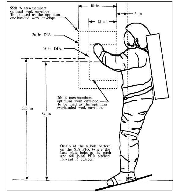
Reference: Derived from NSTS 07700, Volume XIV; Appendix 7, p. 1.5-3; NASA-STD-3000 500
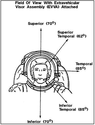
NASA-STD-3000 502
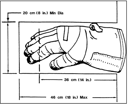
NASA-STD-3000 517
14.3.2.5 EVA Working Envelopes
{A}
The space suit dimensional envelope will play an important role for any task requiring the crewmember to enter into an opening as bight be required during space construction tasks or servicing of large space modules.
The following guidelines define crewmember work envelopes for translation, body entrance,
gloved hand clearance , etc., and should be considered minimum design limits.
a. Minimum Working Envelope - a minimum working envelope of 20 cm (8 in.) diameter by 36 cm (14 in.) deep has been established for the EVA glove. This volume will allow a gloved hand to manipulate most hand-operated controls such as latches switches, buttons, and knobs. See
Figure 14.3.2.3.1-3.
b. Gloved-Hand Clearance - When gloved-hand clearance is required adjacent to ORUs, the following dimensions should be incorporated into the design. Clearance between ORUs, ORU/structures, ORU/Cable, etc., should be at least 20 cm (8 in.) high, no more than 46 cm (18 in.) deep, and 27 cm (10.5 in.) wide.
c. Tool Access - Consideration should be given to the following guidelines:
1. When only tool access is required, a 2.5 cm (1.0 in) minimum clearance should be provided around the fastener or drive stud for insertion, actuation, and removal of the drive end of the tool.
2. A minimum of 7.6 cm (3.0 in) should be provided for clearance between a tool handle engaged on a fastener or drive stud and the nearest piece of hardware. The tool handle should be able to maintain this clearance through a full 180 degree swept envelope.
d. Extensive Manipulation - EVA tasks that involve extensive body and arm manipulation will require a sufficient working envelope. The exact size will depend on the space suit and the type of task performed.
(Refer to Paragraph 12.3.1.2, Physical Accessibility, and
Paragraph 8.6.3.2, Crew Station Body Envelopes, and
Paragraph 11.2.3.6, Tool Access Design Requirements, for other information that pertains to working envelopes.)
14.3.2.6 EVA Head Movement and Viewing Limits
{A}
A crewmember in a space suit has a restricted vision cone due to limitations imposed by the suit, helmet, and visor assembly. For this reason, care must be taken in locating equipment at the workstations and along the translation routes to ensure that all critical hardware are easily seen.
(Refer to Paragraph 9.2.4, Human/Workstation Configuration, for additional information pertaining to viewing limits).
14.3.2.7 EVA Space Suit Measurement Considerations
{A}
Two major approaches have been used in the development and manufacture of space suits. The first approach, used prior to STS, was to use the particular body measurements of each crewmember to build special individualized suits. This resulted in a requirement for a large quantity of suits, the uses of which were limited to a single crewmember.
The second approach, employed for STS EMU's was to use a standard sizing system to accommodate a large number of EVA crewmembers. Individual space suits were made up form a stocked inventory of space suit component parts and assembled to accommodate the anthropometry and comfort of each crewmember. One training and one flight custom-fitted suit was made for each crewmember.
Space suit measurement approaches should consider providing the widest range of space suit components to accommodate the fullest range of potential users with the smallest required inventory of components.
14.3.3 EVA Anthropometry Design Requirements
{A}
The anthropometric data for EVA crewmembers are provided in this section. These include joint motion, movement ranges, neutral body posture, and working envelopes as well as pressure suit dimensions. These data will be used as appropriate to achieve effective integration of the EVA crew and systems.
14.3.4 Example EVA Anthropometric Design Solutions
{A}
This section provides anthropometric dimensions for EVA crewmembers using data from the STS program.
14.3.4.1 STS EMU Dimensions
{A}
The overall spacesuit dimensions for the STS EMU are shown in Figure
14.3.4.1-1. Selected measures which determine STS EMU sizing requirements are shown in
Figures 14.3.4.1-2 a, b, and c. There are 12 standard functions of ingress and egress or attachment by the body measurements and 28 nonstandard anthropometrics used in spacesuit sizing. The 28 nonstandard measures are shown in
Figure 14.3.4.1-3.
Figure 14.3.4.1-1
STS EMU Gross Dimensions (1985 Data for 5th Percentile U.S.
Female and 95th Percentile U.S. Male)
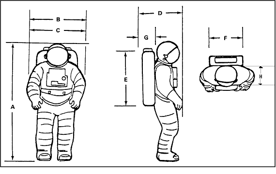
| Size range |
|
5th Percentile Female |
95th Percentile Male |
| A - Height |
171.5 cm (67.5 in) |
191.9 cm (75.5 in) |
| B - Maximum breadth at elbows (arms relaxed) |
-- |
84.8 cm (33.4 in) |
| C - Maximum breadth at elbows (arms at side)
|
-- |
66.0 cm (26.0 in) |
| D - Maximum depth with PLSS/SOP |
66.0 cm (26.0 in) |
68.6 cm (27.0 in) |
| E - PLSS height |
81.c cm (32.0 in) |
| F - PLSS breadth |
58.4 cm (23.0 in) |
| G - PLSS depth |
17.8 cm (7.0 in) |
| H - PLSS to DCM distance (maximum) |
52.8 cm (20.77 in) |
Notes:
PLSS - Primary Life Support System
SOP - Secondary Oxygen Pack
DCM - Display and Control Module |
|
Reference: 145, p. E-24; NASA-STD-3000 306
Figure 14.3.4.1-2
Shuttle Space Suit Anthropometry and Body Measurements
|
a. Number
|
Body measurement
|
Measurement application
|
|---|
|
Hard upper torso (HUT)122
|
Bideltoid breath
|
Shoulder clearance for donning.
|
|
233
|
Chest breath
|
Width clearance at Scye bearings.
|
|
230
|
Chest circumference
|
Chest circumference clearance.
|
|
427
|
Head breadth
|
Head to scye bearing clearance for donning.
|
|
441
|
Head length
|
Front to rear head clearance for donning.
|
|
747
|
Shoulder circumference
|
Shoulder easement for arm-to-hut interface.
|
|
SSA 01
|
Expanded chest depth
|
Chest depth clearance and easement.
|
|
Note: HUT size and selection is of significant importance since it determines the required arm scye opening orientation, the LTA body seal entry closure circumferences and the waist length required
|
|
Lower torso assembly (LTA)
|
|
249
|
Crotch height
|
Leg length and upper and lower length insert size adjustment.
|
|
457
|
Hip breadth
|
Waist bearing circumference.
|
|
873
|
Tibiale height
|
Position of knee in joint.
|
|
SSA 02
|
Vertical trunk diameter
|
Crotch easement.
|
|
SSA 03
|
Mid shoulder height standing
|
Leg length insert size adjustment.
|
|
SSA 04
|
Shoe size
|
Boot and boot insert sizes.
|
|
Liquid cooling ventilation garment (LCVG)
|
|
249
|
Crotch height
|
Leg length easement.
|
|
747
|
Shoulder circumference
|
Trunk easement.
|
|
916
|
Vertical trunk circumference
|
Leg vent duct length insert size.
|
|
SSA 02
|
Vertical trunk diameter
|
Leg vent duct length insert size.
|
|
SSA 04
|
Shoe size
|
Boot and leg vent duct insert size.
|
|
SSA 05
|
Forearm circumference
|
Arm vent duct height profile.
|
|
SSA 06
|
Inter-wrist
|
Arm vent duct length size adjustment.
|
|
Arm assembly
|
|
Arm Scye bearing and upper arm bearing circumferences are determined by the selected HUT size. Lower arm length and HUT/arm assembly sizes are determined by the following:
|
|
SSA 07
|
Inter-elbow
|
Position of elbow in joint.
|
|
SSA 08
|
Inter-fingertip
|
Lower arm length and arm insert size adjustment
|
|
EV gloves
|
|
416
|
Hand circumference
|
Standard size glove selection.
|
|
420
|
Hand length
|
Standard size glove selection.
|
|
SSA 09 through SSA 28 (see below)
|
|
Hand measurements are used for crewmembers requiring custom size gloves.
|
|
SSA 09SSA 10SSA 11SSA 12SSA 13SSA 14
|
Thumb, first knuckle circumference Thumb, second knuckle circumference Thumb length Index finger tip to thumb crotch Index metacarpal knuckle to thumb crotch Index finger first knuckle circumference
|
|
Note: Measurement data - the number adjacent to each of the body measurements are reference codes. Except for the unique SSAXX numbers, the codes are in Volume II of
Reference
16. Reference 16, Volume II, provides additional data for these measurements plus an explanation of the measurement technique. |
Reference: 351; NASA-STD-3000 307a, 1 of 2
Figure 14.3.4.1-2 Shuttle Space Suit Anthropometry and Body Measurements
(Continued)
|
b. Number
|
Body measurement - Measurement application
|
|---|
|
EV gloves (continued)
|
|
SSA 15
|
Index finger second knuckle circumference
|
|
SSA 16
|
Index finger tip to index finger crotch
|
|
SSA 17
|
Middle finger tip to index finger crotch
|
|
SSA 18
|
Middle finger first knuckle circumference
|
|
SSA 19
|
Middle finger second knuckle circumference
|
|
SSA 20
|
Middle finger tip to ring finger crotch
|
|
SSA 21
|
Ring finger tip to ring finger crotch
|
|
SSA 22
|
Ring finger first knuckle circumference
|
|
SSA 23
|
Ring finger second knuckle circumference
|
|
SSA 24
|
Ring finger tip to little finger crotch
|
|
SSA 25
|
Little finger tip to little finger crotch
|
|
SSA 26
|
Little finger first knuckle circumference
|
|
SSA 27
|
Little finger second knuckle circumference
|
|
SSA 28
|
Hand width at metacarpal knuckles
|
Figure 14.3.4.1-2 Shuttle Space Suit Anthropometry and Body Measurements
(Continued)
|
c. Number
|
Body measurement
|
Minimum Cm (inches)
|
Maximum Cm (inches)
|
|---|
|
122
|
Bideltoid breadth
|
40.31 (15.87)
|
59.19 (22.91)
|
|
223
|
Chest breadth
|
26.80 (10.55)
|
42.19 (16.61)
|
|
230
|
Chest circumference
|
85.01 (33.47)
|
114.91 (45.24)
|
|
249
|
Crotch height
|
71.91 (28.31)
|
91.21 (35.91)
|
|
416
|
Hand circumference
|
19.02 (7.49)
|
24.51 (9.65)
|
|
420
|
Hand length
|
16.51 (6.50)
|
21.59 (8.50)
|
|
427
|
Head breadth
|
14.20 (5.59)
|
17.91 (7.05)
|
|
441
|
Head length
|
18.49 (7.28)
|
22.63 (8.91)
|
|
457
|
Hip breadth
|
31.60 (12.44)
|
41.58 (16.37)
|
|
747
|
Shoulder circumference
|
93.29 (36.73)
|
132.00 (51.97)
|
|
805
|
Stature
|
163.50 (64.37)
|
188.70 (74.29)
|
|
873
|
Tibiale height
|
42.90 (16.89)
|
56.90 (22.40)
|
|
916
|
Vertical trunk circumference
|
152.50 (60.00)
|
195.91 (77.13)
|
|
SSA 01
|
Expanded chest depth
|
23.11 (9.10)
|
28.80 (11.34)
|
|
SSA 02
|
Vertical trunk diameter
|
59.79 (23.54)
|
77.50 (30.51)
|
|
SSA 03
|
Mid shoulder height (standing)
|
135.81 (53.47)
|
160.40 (63.15)
|
|
SSA 04
|
Shoe size
|
16.51 (6-1/2)
|
33.02 (13.00)
|
|
SSA 05
|
Forearm circumference
|
18.01 (7.09)
|
32.26 (12.70)
|
|
SSA 06
|
Inter-wrist
|
124.69 (49.09)
|
155.30 (61.14)
|
|
SSA 07
|
Inter-elbow
|
79.20 (31.18)
|
104.50 (41.14)
|
|
SSA 08
|
Inter-finger tip (span)
|
157.81 (62.13)
|
195.58 (77.00)
|
Reference: 351; NASA-STD-3000 307b
Figure 14.3.4.1-3
Space Suit Non-Standard Anthropometrics
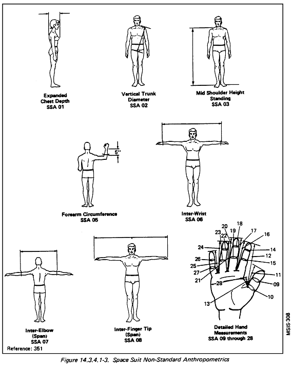
Reference: 351; NASA-STD-3000 308
14.3.4.2 STS EMU Boot Dimensions
{A}
The STS EMU boot heel dimensions are provided in Figure
14.3.4.2-1.
Figure 14.3.4.2-1
STS EMU Boot Interface as an Example Design Solution
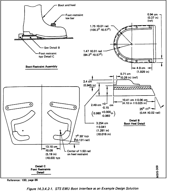
Reference: 100, p. 86; NASA-STD-3000 309
14.3.4.3 Example Pressure Suit Joint Mobility
{A}
The STS EMU provides suit mobility motions of nearly 85% nude body range capability pressurized at 30 kp (4.3 psia) plus or minus 0.7 kPa (0.1 psia).
Mobility capability specifications of the STS EMU are shown in Figures 14.3.4.3-1 and
14.3.4.3-2
Figure 14.3.4.3-1
STS Space Suit Joint Mobility and Torque Specifications at 4.3
psig
|
Item
|
Range
|
Torque
|
|---|
|
Shoulder mobility
|
|
Adduction/abduction
|
2.62 rad (150 deg)
|
1.36 Nm (12 in-lbs)
|
|
Lateral/medial
|
0.35/2.62 rad (20 deg/150 deg)
|
1.36 Nm (12 in-lbs)
|
|
Flexion/extension
|
3.14 rad (180 deg)
|
4.52 Nm (40 in-lbs)
|
|
Rotation (x-z plane)
|
1.57 rad (90 deg)
|
3.39 Nm (30 in-lbs)
|
|
Rotation (y-z plane) (lateral-medial)
|
2.09 rad (120 deg)
|
3.39 Nm (30 in-lbs)
|
|
Elbow mobility
|
|
Flexion/extension
|
2.27 rad (130 deg)
|
1.36 Nm (12 in-lbs)
|
|
Wrist mobility
|
|
Flexion/extension
|
1.57 rad (90 deg)
|
0.68 Nm (6 in-lbs)
|
|
Abduction/adduction
|
2.09 rad (120 deg)
|
0.68 Nm (6 in-lbs)
|
|
Waist mobility
|
|
Flexion/extension (hip and
waist)
|
1.57 rad (90 deg)
|
5.42 Nm (48 in-lbs)
|
|
Rotation
|
2.62 rad (150 deg)
|
12.43 Nm (110 in-lbs)
|
|
Hip mobility
|
|
Flexion
|
1.22 rad (70 deg)
|
2.71 Nm (24 in-lbs)
|
|
Abduction
|
0.17 rad (10 deg)
|
2.71 Nm (24 in-lbs)
|
|
Knee mobility
|
|
Flexion (standing)
|
2.09 rad (120 deg)
|
1.36 Nm (12 in-lbs)
|
|
Flexion (kneeling)
|
2.62 rad (150 deg)
|
1.36 Nm (12 in-lbs)
|
|
Ankle mobility
|
|
Flexion/extension
|
0.70/0.70 rad (40 deg/40 deg)
|
1.36 Nm (12 in-lbs)
|
|
Forearm mobility
|
|
Wrist rotation
|
31.4 rad (180 deg)
|
0.68 Nm (6 in-lbs)
|
|
Glove mobility
|
|
Finger flexion/extension
|
Grasping a one-inch diameter rod for 5 minutes
|
___
|
Reference: 263, Table II, p. 3-20; NASA-STD-3000 310
Figure 14.3.4.3-2
STS Space Suit Joint Mobility Range Specifications for 4.3 psig
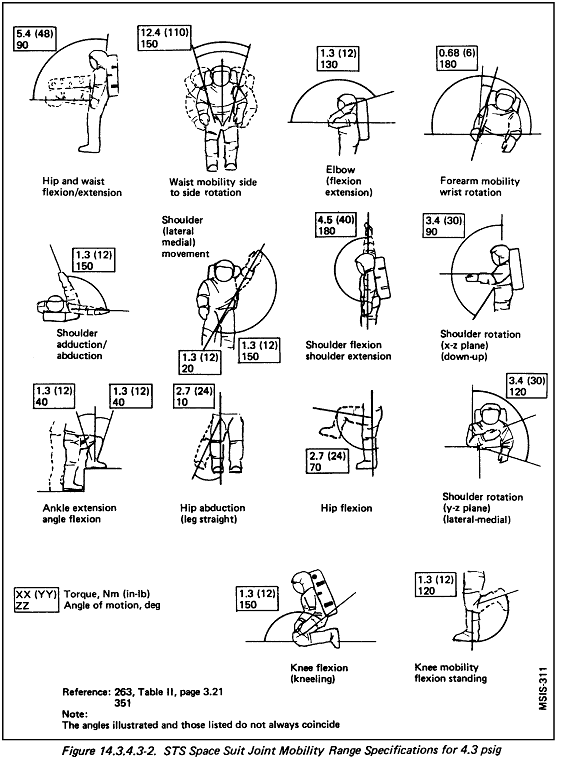
Note: The angles illustrated and those listed do not always coincide.
|
Reference: 263, Table II, p. 3.21; NASA-STD-3000 311
14.3.4.4 STS EVA Helmet Visual Range
{A}
The STS EMU helmet-visor system provides a minimum unrestricted field-of-view (body-fixed) of 120o left and 120o right in the horizontal plane. In the vertical plane, 105o down and 90o up visibility is provided. The EMU visor allows the crewmember to view the EMU boots during EVA workstation and restraint ingress.
STS EVA helmet visual range limitations are presented in Figure
14.3.4.4-1, and EMU field-of-vision is illustrated in Figure
14.3.4.4-2.
Figure 14.3.4.4-1
STS EVA Helmet and Extravehicular Visor Assembly Visual Range Limitations
|
System provision |
Parameter |
Performance |
|---|
|
Helmet and EVA optical visibility
|
Field of vision
|
120 deg. left and right in the horizontal plane. 105 deg. down and 90 deg. up in the vertical plane
|
|
Critical area of vision
|
Vertical
|
90 deg 1.57
rad
|
|
Superior-temporal |
62 deg 1.08 rad |
|
Superior |
85 deg 1.48 rad |
|
Inferior-temporal |
85 deg 1.48 rad |
|
Inferior |
70 deg 1.22 rad |
|
|
|
Optical distortion
|
|
No visible distortion or optical defects detectable by the unaided eye. (20/20 visual acuity) at the typical "as worn" position
|
|
|
|
Transmittance
|
Nanometers (nm)
|
UV
|
Luminous
|
IR
|
|
200-300
|
400-700
|
700+
|
|
|
|
Thermal/coating optical characteristics
|
Characteristics
|
Inner
protective visor
|
Outer
sun visor
|
|
Transmittance
|
|
550
nm
|
70% min.
|
16
±
4%
|
|
1100 nm |
N/A |
10% max. |
|
Solar reflectance
|
|
550
nm
|
5% max.
|
40%
min.
|
|
2400 nm |
70% min. |
N/A |
|
700 nm |
N/A |
55% min. |
Reference: 263, Table II, p. 4-9; NASA-STD-3000 312
Figure 14.3.4.4-2
STS EMU Field-of-Vision as an Example Design Solution
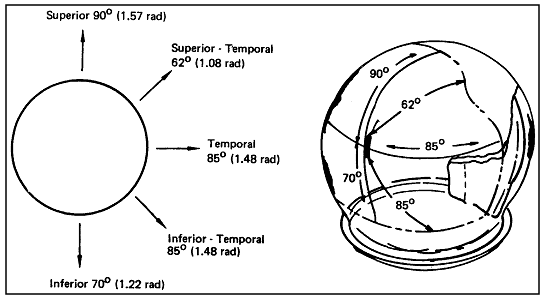
Note: Operational field-of-vision is considerably modified by the
protective extravehicular visor assembly.
|
Reference: 320; NASA-STD-3000 313
14.3.4.5 STS EMU Man Induced Load Examples
{A}
Manload values are derived from tests specifically designed and performed to supply information relating to pressure suit design. In derivation of testing results, the average plus three times the standard deviation was used to represent the 95th percentile male, the worst case design loading. Thorough measurements of manloads have been done for both the Apollo and the STS space suit. The larger of the induced manloads of the two suits is taken as the worst case. A summary of the current design manloads is shown in
Figure 14.3.4.5-1. The higher manloads generally occurred in the Apollo space suit where braided steel cables were used, with much higher stiffness than the fabric restraint lines of the Shuttle suit.
Figure 14.3.4.5-1
Example Load Values for the STS EMU at 4.4 psig
|
Load Values |
|---|
| Location |
Man induced loads |
Plug @ 30.3 kPa
(4.4 psig) |
Total |
|
kg
|
(lbs)
|
kg
|
(lbs)
|
kg
|
(lbs)
|
|
|
|
HUT - Scye Pivot (1)
|
68
|
(150)
|
96
|
(212)
|
164
|
(362)
|
|
HUT - gimbal stop
|
----
|
----
|
----
|
----
|
68
|
(150)
|
|
|
|
Upper arm
|
68
|
(150)
|
44
|
(96)
|
112
|
(256)
|
|
Lower arm
|
68
|
(150)
|
23
|
(50)
|
91
|
(200)
|
|
Arm sizing
|
68
|
(150)
|
23
|
(50)
|
91
|
(200)
|
|
|
|
Waist
|
226
|
(499)
|
195
|
(430)
|
421
|
(929)
|
|
Brief, side
|
136
|
(300)
|
100
|
(221)
|
236
|
(521)
|
|
Brief, fore and aft
|
183
|
(404)
|
195
|
(430)
|
378
|
(834)
|
|
Thigh, inside
|
159
|
(350)
|
71
|
(157)
|
230
|
(507)
|
|
Thigh, sizing
|
159
|
(350)
|
71
|
(157)
|
230
|
(507)
|
|
Thigh, outside
|
136
|
(300)
|
71
|
(157)
|
207
|
(457)
|
|
Leg, inside
|
159
|
(350)
|
27
|
(60)
|
186
|
(410)
|
|
Leg, sizing
|
159
|
(350)
|
27
|
(60)
|
186
|
(410)
|
|
Leg, outside
|
136
|
(300)
|
27
|
(60)
|
163
|
(360)
|
|
Boot, inside
|
159
|
(350)
|
23
|
(50)
|
181
|
(400)
|
|
Boot, outside
|
136
|
(300)
|
23
|
(50)
|
159
|
(350)
|
|
|
|
Glove (1) |
|
Axial restraints |
40.6 |
(89.6) |
22.5 |
(49.6) |
61.8 |
(136.2) |
| Finger cap |
12.0 |
(26.4)
|
2.3
|
(5.1)
|
14.3
|
(31.3)
|
|
Thumb cap
|
35.1
|
(77.4)
|
3.2
|
(7.1)
|
38.3
|
(84.2)
|
|
Finger crotch
|
16.0
|
(35.2)
|
6.0
|
(13.3)
|
22.0
|
(48.0)
|
|
Thumb crotch
|
33.1
|
(73.0)
|
6.0
|
(13.3)
|
39.1
|
(85.8)
|
Reference: 320; NASA-STD-3000 314
14.4 EVA WORKSTATIONS AND RESTRAINTS
{A}
14.4.1 Introduction
{A}
This section establishes design criteria for EVA workstations and crew restraints. For the purpose of this section, and EVA workstation will be defined as any area where pressure-suited tasks will be performed, including space suit controls and displays. A restraint will be defined as a means of stabilizing an EVA crewmember that requires physical crewmember.
14.4.2 EVA Workstation and Restraint Design Considerations
{A}
EVA workstations should be designed to optimize task performance. Workstations and restraints should be designed on the basis of an EVA crewmember's safety considerations and performance capabilities and limitations
The following factors should be considered in the design of EVA workstations and restraints:
a. EVA Work Envelope - The reach, mobility, and field-of-view restrictions imposed by a pressure suit, and the effect of neutral body posture on the line-of-sight should be considered in workstation and restraint design.
b. Hardware Design for EVA Access - Hardware intended for EVA repair or replacement should be designed to facilitate access by suited crewmembers and should provide for EVA tool access.
c. EVA Controls and Displays - The location and configuration of controls and displays at an EVA workstation should be based on EVA crewmember and suit-imposed capabilities and limitations.
d. EVA Workstation Lighting - Adequate lighting should be provided at worksites to optimize task performance and preclude visual fatigue.
e. EVA Crew Restraints - Appropriate crew restraints are necessary for optimal task performance.
14.4.2.1 EVA Work Envelope Design Considerations
{A}
The work envelope, mobility range, and visual field-of-view of the suited crewmember should be considered in workstation design.
EVA workstations should be designed to accommodate the characteristics of the suited female and the suited male user population.
The effects of neutral body position on the EVA crewmember's line-of-sight should be taken into consideration in workstation design.
(Refer to Paragraph 9.2.4, Human/Workstation Configuration, and
Paragraph 8.6.2, Envelop Geometry Design Consideration, for other considerations that pertain to work envelopes).
14.4.2.2 Hardware Design Considerations for EVA Access
{A}
Hardware to be manipulated by an EVA crewmember should be designed to facilitate its use, removal, or replacement by a space suited crewmember.
a. Reach and Mobility - Hardware should be within the reach envelope and mobility constraints imposed by the crewmember size, the space suit design, and crew restraints.
b. Clearance - Sufficient clearance should be allowed around the hardware for access by a space suited gloved hand.
c. Tools - Physical access required for EVA tools should be provided.
d. Handholds and Tether Attach Points - These should be located at each EVA workstation.
e. Visual - Access to see the work space, components, and tools necessary for task accomplishment should be provided.
(Refer to Paragraph 12.2, Design for Maintainability - Design Considerations, for additional information that pertains to hardware and equipment.)
14.4.2.3 EVA Controls and Displays Design Considerations
{A}
EVA controls and displays are similar to those for IVA, but should be designed based on the following considerations:
a. Space Suit-Controls Interface-EVA control size, clearances, location, type, and actuation force should be based on the limitations imposed by the space suit and glove on the EVA crew member.
b. Displays - Display location should be based on the visual restrictions imposed by the space suit.
c. Labeling - Labeling and color coding of EVA controls and displays should be consistent with IVA labeling, when possible, considering environmental visual factors such as glare, contrast, and illumination available.
d. Space Suit Controls - Controls - Controls mounted on the EVA space suit should be within the field of view of the suited crewmember.
(Refer to Paragraph 9.2.3, Control/Display Placement and Integration, and
Paragraph 9.5, Labeling and Coding, for other considerations that pertain to hardware controls and displays.
14.4.2.4 EVA Workstation Lighting Design Considerations
{A}
Lighting requirements at EVA workstations may be provided by direct or reflected solar illumination, permanently mounted lights, portable lights, or a combination of these sources.
The following factors should be considered in the design of workstations lighting:
a. Orbital Condition - Lighting should be adequate for both day and night orbital conditions.
b. Required Illumination - Level of illumination required is task-specific.
c. Specular glare is created when the image of a light source is reflected from a surface in the visual field. Direct glare is produced by a light source located within the visual field. Provisions should be made for reducing both types of glare.
d. Luminance Ratio - The ratio between the luminance of objects and the surrounding area. A luminance ratio should be set that optimizes performance for the level of task detail. Higher luminance ratios are desirable for finer detail work.
e. Contrast - The difference between the luminance an object or feature and its background. Human attention tends to be attracted to high contrast elements in the visual environments.
(Refer to Paragraph 8.13.2, Lighting Design Considerations, for other considerations that pertain to workstation lighting.)
f. Safety - The lack of convective currents to take away heat means that physical protection should be provided to eliminate any thermal safety hazards.
g. Exterior Light Controls - Light controls for permanently installed exterior lighting should be located both at the exterior and interior of the space module at convenient locations.
14.4.2.5 EVA Crew Restraint Design Considerations
{OP}
Proper restraint of the EVA crewmember at the workstation is essential for successful microgravity EVA operations. Failure to provide adequate restraint can be the single most limiting factor of all EVA design elements. Inadequate restraint induces unnecessarily high workloads and may lead to crew fatigue, overloading of the life support system, and premature termination of the EVA. Inadequate restraint also increases the potential for equipment damage during EVA operations.
Restraints for each workstation should be selected on the basis of the task to be performed. Tethers and handholds may be adequate for short-term tasks such as inspection and monitoring. Foot restraints should be provided for tasks requiring moderate-to-heavy force application and long-term positioning.
Preinstalled handholds and handrails should be used. Crew-attached or portable handrails, handholds, and foot restraints should be considered for non-routine or unplanned EVA workstations.
Handholds should be provided for ingress/egress of food restraints.
(Refer to Paragraph 11.7.2.2, Personnel Restraints Design Considerations,
Paragraph 8.9.2, Mobility Aids and Restraint Integration Design Considerations; and
Paragraph 11.8.2.1, Handhold and Handrail Design Considerations for other restraint and mobility aid design considerations.)
14.4.3 EVA Workstation and Restraint Design Requirements
{A}
This section defines the design requirements for EVA workstations and restraints. Requirements driven by EVA anthropometry, crew restraints, hardware design for EVA access, control and display specifications, and lighting required at the workstation are included.
(Refer to Paragraph 9.2.3, Control/Display Placement and Integration, for other requirements that may pertain to controls and displays.)
14.4.3.1 EVA Work Envelope Design Requirements
{A}
EVA workstations shall be designed based on the reach envelopes, field-of-view, and neutral body posture of the space suited crewmember defined in
Paragraph 14.3.2.2.
(Refer to Paragraph 9.2.4.2, Human/Workstation Configuration Design Requirements, and
Paragraph 8.6.3.1, Crew station Body Envelopes Design Requirements, for other requirements that pertain to envelope geometry.)
14.4.3.2 EVA Control and Display Design Requirements
{A}
EVA control and display designs shall include the following:
a. Controls - EVA control type, location, and actuation forces shall conform to the EVA requirements in
Paragraph 9.2, Workstation Layout, and
Paragraph 9.3, Controls, with the following additions and exceptions to those requirements:
1. Glove Interface - All controls with the potential to be operated by an EVA crewmember shall be operable by a crew member wearing a pressurized EVA space suit glove.
2. Switches - Guarded switches shall be employed where possible. Switches shall provide tactile and/or visual feedback of position.
3. Mechanical Feedback - Mechanical control feedback shall be sufficient to override space suit glove attenuation so that the EVA crewmember receives positive indication that the control function is completed. The mechanical feedback actuation force shall be detectable but not less that 15.5 N (3.5 lbs.).
4. Load - EVA controls shall withstand crew-imposed loads of 1,254 Newtons in all directions or be protected from these loads.
5. Inadvertent Actuation - Protection shall be provided for all EVA controls to prevent inadvertent actuation. Toggle switches mounted on the pressure suit in sagittal or the transverse plane shall have their normal EVA operational position toward the crewmember.
6. Reach Envelope - EVA controls shall be located within the visual and reach envelope of the potential EVA crew population.
7. Spacing - Control spacing shall permit selective operation of individual controls by a space suited crewmember.
b. Displays - EVA display type and location shall conform to the IVA display requirements in
Paragraph 9.4.2.3 of this document, with the following additions/exceptions:
1. Type - EVA display type shall be appropriate for the EVA task performed.
2. Loads - EVA displays shall withstand crew-imposed contact loads in all directions or be protected from these loads.
3. Field-of-View - EVA displays shall be located within the field-of-view permitted by the pressure suit and restraint system.
4. Readability - EVA displays shall be readable over the range of lighting extremes expected.
(Refer to Paragraph 9.2.3.2 Control/Display Placement and Integration Design Requirements, for additional requirements on field-of-view.)
c. Labeling - Labeling and color coding at EVA workstations shall conform to the IVA labeling and coding requirements in
Paragraph 9.5 and sub-paragraphs of this document, with the following exceptions:
1. Attachment - EVA labels shall be mechanically or permanently attached to the mounting surface.
2. Color Coding - Color coding shall be used only when adequate white illumination is available at the EVA workstation.
14.4.3.3 EVA Workstation Lighting Design Requirements
{A}
(Refer to Paragraph 9.2.2.2.1, Workstation Illumination, for other requirements that pertain to lighting and illumination.)
Illumination categories and value ranges for generic EVA activities are presented in
Figure 14.4.3.3-1, and minimum illumination levels for EVA tasks are given in
Figure 14.4.3.3-2.
Figure 14.4.3.3-1
Illuminance Categories and Value Ranges for Generic EVAs
|
Type of activity
|
Illuminance range
|
| Lux |
(fc) |
| Translate a corridor |
33 - 55 |
3 - 5 |
| Lowlight work areas
with occasional simple visual tasks |
55 - 110 |
5 - 10 |
| Visual tasks with
large size or high contrast objects |
215 -
325 |
20 - 30 |
| Visual tasks with
small size or medium contrast objects |
325 -
750 |
30 - 70 |
| Visual tasks with very
small size or low contrast objects |
540 -
1080 |
50 -
100 |
| Visual tasks with
objects of very small size and low contrast over a prolonged period |
1080 -
2150 |
100 -
200 |
Reference: 320; NASA-STD-3000 315
Figure 14.4.3.3-2
Minimum Illuminance Levels for EVA Tasks
|
EVA Tasks *
|
Minimum Illuminance
|
|---|
|
Lux
|
(fc)
|
|
Astronaut movement to worksite for satellite repair mission or cargo transfer
|
55 - 110
|
5 - 10
|
|
Astronaut positions satellite in cargo bay or station worksite area
|
215
|
20
|
|
EVA satellite servicing worksite; hand tool utilization for simple, non-hazardous repair missions
|
325
|
30
|
|
EVA satellite servicing worksite; use of new and complex tools, non-hazardous
|
540
|
50
|
|
EVA satellite servicing worksite; complex tools and hazardous tasks
|
810
|
75
|
Reference: 320; NASA-STD-3000 316
Additional illumination requirements include:
a. Lights - EVA workstations shall be illuminated by permanently mounted and/or portable lights. Illumination shall be adequate for task-specific requirements during both day and night conditions.
b. Glare - EVA lighting shall not cause excessive glare or create any other annoyance to the crew.
c. Field-of-View - Light sources at workstations shall not be located within 1.05 radians (60 degrees) of the center of the crewmember's field-of-view.
d. Diffuse Lighting - Diffuse lighting shall be used and highly polished surfaces shall be avoided.
e. Fixtures - Light source shall provide even illumination. Fixtures shall be designed to direct light into the desired area without causing visual discomfort to the crew. Light fixtures located close to workstations shall be designed to protect the crewmembers from thermal and physical hazards.
f. Lumination Ratio - The luminance ratio at workstations shall conform to the following minimum specifications:
1. 3:1 between task areas and immediate surround.
2. 5:1 between task area and adjacent surround.
3. 10:1 between task areas and remote surfaces.
4. 20:1 between light sources and immediate adjacent surfaces.
g. Portable Lights - Portable lights shall be provided for unplanned maintenance, emergencies, and task performance where adequate fixed illumination is not available.
h. Exterior Light Controls - Light controls for permanently installed exterior lighting shall be located both at the exterior and interior of the space module at convenient locations.
i. Light Beam Spread - The lighting system shall have sufficient beam spread from a normal plane to provide the crewmember with good peripheral visual orientation.
14.4.3.4 EVA Crew Restraint Design Requirements
(OP)
The use and design of EVA crew restraints shall conform to the following requirements:
(Refer to Paragraph 8.9.3, Mobility Aids and Restraints Architectural Integration Design Requirements, and
Paragraph 11.7.2.3, Personnel Restraint Design Requirements, for other requirements.)
a. Force Exertion - Foot restraints shall be used for actuation or operation of equipment which requires the crewmember to exert forces exceeding those given in
Figure 14.4.3.4-1. EVA waist tether restraint systems may be used when actuation or operation of equipment does not require forces and durations greater than those specified in
Figure 14.4.3.4-1.
Figure 14.4.3.4-1
Maximum Forces and Duration Capable of a Tethered but Free-Floating
EVA Crewmember
|
Linear force
|
Duration
|
|---|
|
4.4 N (1.0 lbf)
|
4.5 sec
|
|
22.2 N (5.0 lbf)
|
2.1 sec
|
|
44.5 N (10.0 lbf)
|
1.4 sec
|
Reference: 253, p. 5-9; NASA-STD-3000 317
b. Foot Restraints - EVA foot restraints:
1. Shall be designed to permit easy insertion and removal of pressure suit boots by the crewmember.
2. Shall accommodate all boot sizes.
3. Shall require a deliberate action for removal of a boot.
4. Shall provide a contingency method for removal of a jammed boot from a foot restraint.
5. Shall provide the capability to react to loads applied by the crewmember.
(Refer to Paragraph 11.7.2.3.2, Foot Restraint Design Requirements, for other requirements.)
c. EVA Safety Tethers and Safety Hooks - Tethers and tether hooks:
1. Shall have a handle that will fit the gloved hand of a space-suited crewmember, allow the hook to be free for utilization, and have a minimum length of 9.5 cm (3.75 in.).
2. Shall have design features that indicate whether the latch lock is engaged or disengaged, and to indicate direction for engaging and disengaging the lock.
3. Safety tether attachment hooks shall be removed and attachable by one-handed operation and employ a redundant lock feature such as push-to-open buttons that must be operated to disengage or release a tether.
4. Shall provide a contingency method for removal of a snagged tether or release of a crewmember from a tether hook.
d. Airlock - Provide handrails and tether attach points and other personnel restraints at the interior and exterior of the airlock.
e. EVA Suit Don and Doff - Provide personnel and equipment restraints at the EVA space suit facility.
14.4.3.5 EVA Equipment Tether Design Requirements
{A}
EVA equipment tethers shall be designed to the following requirements:
a. One-Handed Operations - All EVA equipment tethers shall be designed such that tether attachment and removal methods permit one-handed operation using a pressure suit glove.
b. Common Attachment Point - All EVA equipment tethers shall use a common attachment method.
c. Tether Attachment Points - All equipment items shall be provided a standardized tether hook receptacle shown in
Figure 14.4.3.5-1. This standardized receptacle shall also be provided on the interfacing surface to which the item is to be secured.
d. Tether Lock Status Indicator - The tether lock shall be designed in such a way that it will be easy to recognize when the hook is locked/unlocked in body day and night lighting conditions.
Figure 14.4.3.5-1
STS Space Suit Helmet Mounted Lights
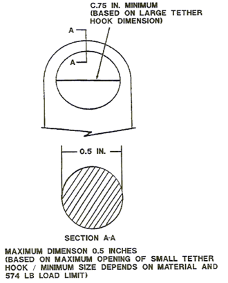
Text: Maximum dimension 0.5 inches (based on maximum opening of small
tether hook / minimum size depends on material and 574 lb load limit).
C.75 in. minimum (based on large tether hook dimension).
|
NASA-STD-3000
14.4.4 Example EVA Workstation and Restraint Design Solutions
{A}
Included in this section are EVA workstation lighting and restraint designs that have been successfully employed in the past.
14.4.4.1 EVA Workstation Lighting Example Design Solutions
{A}
EVA lighting requirements have been satisfied in the STS program through permanently mounted and portable lights. Seven cargo bay flood lights provide a minimum of lux (541 fc.) at the cargo bay centerline and the bulkhead light provides 580 lux (54 fc.) at 9.1 m (30 ft.).
Lights mounted on the space suit helmet have been employed to supplement permanently mounted lights. The four EMU lights, shown in
Figure 14.4.4.1-1, are directionally adjustable and provide varying levels of illumination through light combination selection. Each of the four lamps produces 215 lux (20 fc.) at 1 m (3 ft.).
Figure 14.4.4.1-1
STS Space Suit Helmet Mounted Lights
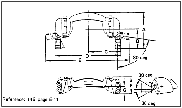
|
| Technical Information |
| Part number |
10161-10061-04 |
| Weight |
2.27 kb (5 lb) (without main batteries)
2.67 kb (5.88 lb) (with main batteries) |
| Quantity flown |
Two in the middeck Volume H locker |
| Main power supply |
Two independent battery modules (one per side) |
| Main batteries |
D-size lithium bromine complex (3.5 V, 8 A-hr each) |
| Battery life |
3 hr min with four lamps operating |
| Voltage |
| Open circuit |
3.77 ± 0.2 V dc |
| Loaded |
3.25 V dc |
| Lamps |
Two halogen lamps per side (2.5 W each) |
| Lamp intensity |
215 LUX (20 ft-c (min)) per lamp at 91 cm (3 ft) |
| Lamp life |
20 hr |
| Lighting pattern |
41 cm by 61 cm (16 in by 24 in at 2 ft) (four lamps on
pointed forward) |
| Operation |
Momentary switch activated sequencing circuit on each side |
| Sequencer power supply |
Four watch batteries in series per side |
| Sequencer battery |
Silver oxide (1.5 V Duracell, 38 mA-hr) |
| Thermal protection |
71 deg C ± 2 deg (160 deg F ± 5 deg)
thermostats and mutilayer insulation |
| Structural F S |
1.4 |
| Dimensional data |
| A |
22.38 cm
(8.81 in) |
| B |
11.84 cm
(4.66 in) |
| C |
19.71 cm
(7.76 in) |
| D |
39.42 cm
(15.52 in) |
| E |
50.24 cm
(19.78 in) |
| F |
10.92 cm
(4.3 in) |
| G |
4.78 cm
(1.88 in) |
Reference: 145, p. E-11; NASA-STD-3000 318
A second example of portable lighting is the EVA flashlight, shown in Figure
14.4.4.1-2. The light is mounted on a flexible neck and a mirror is provided to further aid visibility into inaccessible areas.
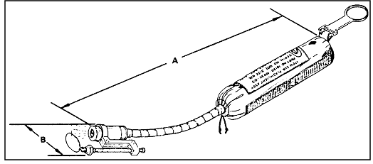
|
| Technical Information |
| Part number |
10172-20561-02 |
| Weight |
0.13 kg (0.26 lb) |
| Battery |
Two AA alkaline wrapped with Teflon and Kapton, 1.5 V each |
| Battery life |
2 yr |
| Lamp |
Standard flashlight bulb |
| Operation |
Rotate bulb housing |
| Quantity flown |
One for STS 41-G, 51-A, 51-I |
| Stowage |
Middeck locker |
| Dimensional data |
| A |
30 cm
(12 in) true length |
| B |
3.56 cm
(1.40 in) |
Reference: 145, p. F-1; NASA-STD-3000 319
14.4.4.2 EVA Crew Restraint Example Design Solutions
{OP}
The portable foot restraint (PFR) is a working platform that restraints the crewmember during the performance of EVA tasks.
A two-axis (roll and pitch) gimbal system with lock knobs is provided for adjustment and positioning. The PFR is shown in
Figure 14.4.4.2-1.
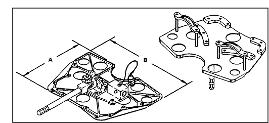 |
| Technical Information |
| Part number |
10159-10034-01, -02 |
| Weight |
3.8 kg (8.4 lb) |
| Material |
Aluminum alloy |
| Input Load |
10176 configuration - 45 kb (100 lb), any direction
10155 configuration - 11 kb (25 lb), any direction |
| Quantity flown |
One |
| Stowage |
Orbiter forward bulkhead |
| Dimensional data |
| A |
40.49 cm
(15.94 in) true length |
| B |
52.07 cm
(20.5 in) |
|
Reference: 145, pages 25-26; NASA-STD-3000 320
An EVA waist tether is shown in Figure
14.4.4.2-2. The tether is made of Nomex webbing and is approximately 91 cm (36 in.) long. Opening of the two hooks requires that the push-to-open buttons on each side be depressed simultaneously while the hook is squeezed. The larger hook attaches to the space module and the smaller hook attaches to the EMU. Two waist tethers may be attached to the EMU.
 |
| Technical Information |
| Part number |
10151-20040-05 |
| Weight |
0.42 kg (0.93 lb) |
| Material |
Normex webbing strap, aluminum hooks |
| Webbing breaking strength |
635 kb (1400 lb) |
| Load limit before extension |
34 kb (75 lb) |
| Operational load limit |
265 kb (585 lb) |
| Quantity flown |
Two for each EMU |
| Dimensional data |
| A |
12.70 cm
(5.00 in) |
F |
3.30 cm
(1.30 in) |
| B |
normal - 60.96 cm
(24.00 in)
break-away - 127.00 cm (50 in) |
G |
1.91 cm
(0.75 in) |
| C |
18.42 cm
(7.25 in) |
H |
1.78 cm
(0.70 in) |
| D |
10.16 cm
(4.00 in) |
I |
3.81 cm
(1.50 in) |
| E |
13.34 cm
(5.25 in) |
J |
5.84 cm
(2.30 in) |
|
Reference: 145, p. W-1; NASA-STD-3000 321
14.4.4.3 EVA Equipment Tether Hook Example Design Solution
{OP}
Figure 14.4.4.3-1 describes the general specification of the EVA equipment tether hook.
Figure 14.4.4.3-1
STS EVA Equipment Tether Hook General Specifications
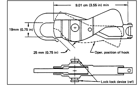 |
| Parameter |
Design requirements/remarks |
| Dimensions |
Handle length shall be 9.5 cm (3.75 in) minimum
to fit in pressurized glove and allow hook to be clear for operation.
Hook diameter recommended 19 mm (0.75 in) minimum for attachment to
Orbiter tether attach points. |
| Design load limit |
Dependent on intended use. Crew man
safety tethers designed for 2610 N (585 lb) ultimate. Recommend 330
N (75 lbs) minimum for equipment tethers |
| Operation |
Hook must allow one-handed operation by a
suited crewman. |
| Safety |
Hook should employ lock-lock feature such that
no single inadvertent action could open hook. |
| Materials |
EVA tether hooks will primarily be manufactured
from metals. |
Reference: 100, p. 89; NASA-STD-3000 322
14.5 EVA MOBILITY AND TRANSLATION
{A}
This section details the design considerations and requirements for EVA mobility and translation. EVA translation routes, aids, and restraints are discussed. The EVA airlock, passageways, and equipment transfer are also included.
14.5.1 Introduction
{A}
14.5.2 EVA Mobility and Translation Design Considerations
{A}
The capabilities of the suited crewmember should be taken into consideration in the design of translation and equipment transfer tasks and hardware.
14.5.2.1 EVA Translation Route Design Considerations
{A}
a. Cross Section of the Translation Route - The cross section of a translation route should have enough clearance for unimpaired movement. The selection of dimensions must consider the number of crew translating simultaneously along its route, the size of the space suit to be used, the size of equipment that may be in the translation path simultaneously, and the intrusion of translations aids into the path.
Figure 14.5.2.1-1 show the definitive dimensions. The translation path dimension Y is determined by the following:
Y = # EMUs x (M+T) + # MAX Equipment x S + C where M is the depth of the EMU with the hands at the chest, T is the translation aid intrusion dimension, S is the equipment dimension, and C is the clearance. The required clearance is design specific. A circular corridor and a square corridor will require different clearances depending on the corridor dimensions selected, the EMU and the equipment configuration.
b. Translation Paths Bottlenecks - When a program selects the design of translation paths, consideration of the human productivity loss associated with bottlenecks in frequently traveled paths should be made.
c. EVA Hatches and Doors - Hatches and doors should be sized to provide adequate clearance for easy transfer. Hatches between space and the crew compartment should be hinged such that the higher pressure of the crew compartment aids in the sealing of the hatch to provide crew assist for this function. The EVA hatches should be easy to operate from either side with disassembly of actuators possible (emergency ingress) from the outside. Thermal protection of the hatch should not encumber the ingress/egress operation.
Figure 14.5.2.1-1
Clearances Required for Selected EVA Translation Routes
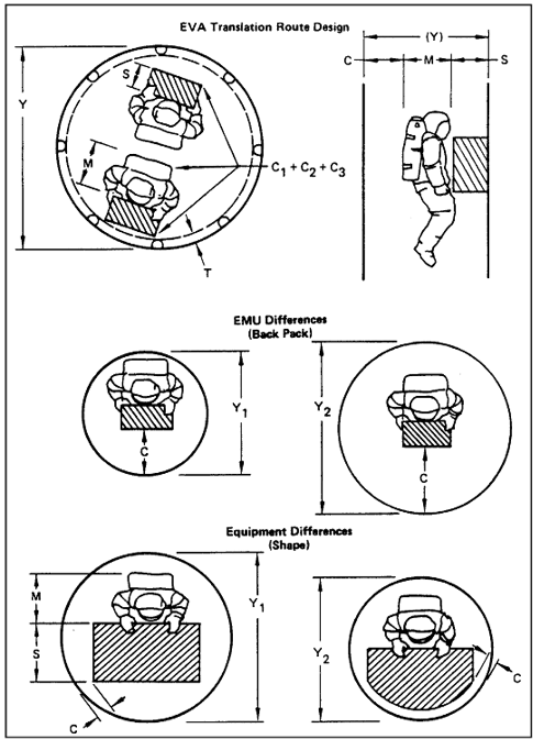
Reference: 320; NASA-STD-3000 323
14.5.2.2 EVA Mobility Aids Design Considerations
{A}
The greatest momentum of the largest combination of EVA crew and transported objects should be considered when establishing the design loads for the mobility aids and aid attachments.
Mobility aids, along a possible EVA crew translation route, should at least consider the design load required for the rescue of another EVA crewmember.
Mobility aids should be designed and positioned to provide translation stability at the translation rates expected for the translation route and through direction changes in the route.
The space suit glove interface should determine the dimensional design of manual mobility aids.
(Refer to Paragraph 8.9.2, Mobility Aids and Restraints Integration Considerations, and
Paragraph 11.8, Mobility Aids, for other considerations that pertain to mobility aids).
14.5.2.3 EVA Translation Restraints Design Considerations
{A}
Appropriate crew safety restraints should be provided for all translation routes to ensure crew safety. Restraints should be provided for EVA equipment, and transferred equipment.
The greatest momentum of the largest combination of EVA crew and transported objects should be considered when establishing the design loads for the restraints and restraint attachments. Restraints along possible EVA crew translation routes should at least consider the design loads required for the rescue of another EVA crewmember.
Translation aids should be designed and positioned to minimize interference with the stability of translation at the expected translation rates even through direction changes.
Translation restraints design and position should be such that the least number of engagements/disengagements are needed to minimize the risk of failure to attach in micro- gravity. Restraints should be positioned such that the crewman is restrained at all times. Consideration should be given to minimizing the crew time required to establish the restraint and to confirm completed engagement.
Appropriate crew restraints, usually safety tethers, should be provided for all translation routes to ensure crew safety and to facilitate crew translation and equipment transfer.
(Refer to Paragraph 8.7.2, Traffic Flow Design Considerations;
Paragraph 8.8.2, Translation Path Design Considerations;
Paragraph 8.9.2, Mobility and Restraints Integration Considerations;
Paragraph 8.10.2, Hatches and Doors Design Considerations; and
Paragraph 11.8, Mobility Aids, for other considerations pertaining to restraints and mobility.)
14.5.2.4 EVA Airlock Design Considerations
{A}
Airlocks provide the means for the EVA crew to transfer from the IVA environment to the EVA environment without depressurizing the crew compartment. Many aspects of air- lock design are critical emergency and safety items. Considerations are:
a. Volume considerations as a function of the EVA systems.
b. Contingency operations of hatches by an EVA crewmember.
c. The airlock hatches should accommodate the passage of two space suited crewmembers to provide the rescue of a disabled crewmember.
d. Refurbishment of the EVA System.
e. Servicing, checkout and stowage of the EVA system.
f. Additional volume and restraints should be considered for EVA transfer of hardware into, through, and out of airlocks.
14.5.2.5 EVA Passageway Design Considerations
{A}
A passageway is a pass-through area between two nonadjacent compartments. A tunnel is a passageway that permits translation by crewmember only along his or her longitudinal axis.
Passageway and tunnel design should take into consideration the clearance required for a suited crewmember and the mode of transit.
Because EVA pressure suits are continually improved and redesigned to meet specific program requirements, specific passageway diameters cannot be fixed. A multiplicative factor can be calculated for determining passageway diameters in which the clearance provided is a percentage of the suited crewmember.
Consideration should be given to the bottleneck impacts on crew productivity before EVA passageways are designed for only one crewmember.
(Refer to Paragraph 8.8, Translation Paths, for additional considerations on passageways.)
14.5.2.6 EVA Equipment Transfer Design Considerations
{A}
Appropriate crew mobility aids (Paragraph 14.5.2.2), restraints
(Paragraph 14.5.2.3) and the design of the equipment being transferred are the key elements in successful EVA equipment transfer operations. Previous experience indicates that the EVA crewmember can successfully transfer a large variety of equipment.
The designer of hardware for EVA should consider module size, quantity, geometry, transfer distance, transfer time, temporary stowage, number of crewmembers required, and handhold and tethering provisions.
(Refer to Paragraph 11.8.3.1, Equipment Mobility Aid Design Considerations, and
Paragraph 8.7.2.3, Equipment Transfer Design Considerations.)
14.5.3 EVA Mobility and Translation Design Requirements
{A}
14.5.3.1 EVA Translation Route Design Requirements
{A}
EVA translation routes shall conform to the following requirements:
(Refer to Paragraph 8.7.3, Traffic Flow Design Requirements, and
Paragraph 8.8.3, Translation Path Design Requirements, for other requirements that may pertain to translation route design.)
a. Equipment - All equipment located along EVA translation routes shall be designed to withstand repeated use as mobility aids, or the equipment shall be guarded or protected. There shall be no protrusions, corners, or sharp edges along EVA translation routes.
(Refer to Paragraph 6.3.3, Mechanical Hazards , for related requirements.)
b. Translation and Mobility Aids :
1. Mobility aids shall be located at terminal points and direction change points on established crew translation paths.
2. Mobility aids shall be placed in all locations where equipment is not available as a substitute.
3. For EVA translation, mobility aids shall not be separated by more than 90 cm (36 in.). The preferred spacing is 60 cm (24 in.).
c. Handholds:
1. The orientation of translation and mobility handholds shall be such that the body position normally assumed to perform a task may be attained, and that normal body movement may be accommodated.
2. They shall also be oriented such that the plane formed by the handhold longitudinal axis and the cross-section major axis is approximately parallel with the body torso frontal plane.
d. Danger Warnings:
1. Translation and mobility handholds located within 30.5 cm (12 in.) of flight equipment shall be identified and color coded (regarding danger of injury to the crewmember due to equipment failure).
2. Equipment located along translation routes that could be damaged by a translating crewmember shall be identified and color coded.
e. Cross Section of the Translation Route - the dimension of the translation route (see
Figure 14.5.3.1-1) shall not be smaller than the dimension required for the EVA crewmember to reverse direction (EMU height + clearance). The exceptions to this are:
1. Corridors where access is possible from either side and the length is no more than twice the length of the smallest EVA suited crewmember.
2. Corridors that have access from at least one end and are not longer than the shortest EVA suited crewmember.
f. EVA Hatches and Doors - The EVA hatches shall be operable form either side of the hatch. EVA translation aids shall be placed around the hatchway on both sides to support ingress/egress.
The latch mechanism shall require less than 110 Newtons (25 lbf) to operate. Opening the hatch shall not require more than 200 Newtons (45 lbf), and closing the hatch shall not require more than 200 Newtons (45 lbf).
g. Equipment Accessibility - Translation and mobility handholds shall be positioned such that crew-operated equipment and consoles are accessible and are not obstructed visually or physically by the handholds.
Figure 14.5.3.1-1
Cross-Section of the EVA Translation Route
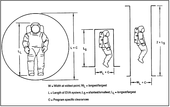
Reference: 320; 351; NASA-STD-3000 324
14.5.3.2 EVA Mobility Aids Design Requirements
{A}
EVA handholds/handrails shall conform to the following design requirements:
(Refer to Paragraph 11.8.2.2.1, Handhold and Handrail Dimensional Design Requirements, and
Paragraph 8.9.3, Mobility Aids and Restraints Design Requirements, for other handhold dimensions that may pertain to EVA mobility requirements.)
a. Dimensions - EVA handhold and handrail dimensions shall conform to Figure
14.5.3.2-1.
b. Mounting Clearance - The minimum clearance distance between the low surface of the handrail/handhold and the mounting surface is 5.7 cm (2.25 in.).
c. Spacing for Translation - For EVA translation, handholds/handrails shall not be separated more than 92 cm (36 in.). Maximum spacing of 61 cm (24 in.) is preferred.
d. Spacing for Worksites - Handrails/handholds shall not exceed 45.8 cm (18 in.) above or below the shoulder or 61 cm (24 in.) to the left or right of the body centerline when working in a foot-restraint position.
e. Safety Tether Attachment - EVA handrails/handholds will accommodate safety tether hooks at a spacing not to exceed 90 cm (36 in) preferred 60 cm (24 in).
f. Lighting - EVA handholds/handrails shall be illuminated in accordance with
Paragraph 14.4.3.3.
g. Color - EVA handholds/handrails shall minimize specular reflection and shall be a standard color throughout the space modules, be clearly visible, and have a high visual contrast with the background.
h. Temperature - Surface temperature of EVA handholds/ handrails shall be compatible with the touch-temperature limits required by the space suit glove.
(Refer to Paragraph 14.2.3.11, EVA Touch Temperature and Pressure Design Requirements, for specified EVA glove temperature requirements).
Figure 14.5.3.2-1
Standard EVA handhold Dimensional Requirements
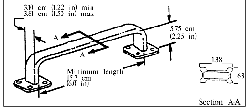
Note: Dimensions ± 0.15 cm (±0.060 in)
|
Reference: 1, Figure 4.1-6, p. 4.1-3; 100,
Table 11.2-1, p. 80; NASA-STD-3000 512
14.5.3.3 EVA Translation Restraints Design Requirements
{A}
Except for free flying maneuvering unit operation, EVA crewmembers in microgravity environments shall always be attached or otherwise restrained to the space module. Safety tether points shall be located as follows:
a. Translation Routes - No more than 90 cm (36 in.) between EVA translation aids, 60 cm (24 in.) preferred.
b. Direction Change - At either side of a directional change in equipment transfer or a distinct hand-off point.
c. Equipment Transfer Paths - At the extreme ends of equipment transfer paths.
d. Tethers and Tether Hooks - Translation route tethers and tether hooks shall conform to the requirements in
Paragraph 14.4.3.5, EVA Crew Restraint Design Requirements.
14.5.3.4 EVA Airlock Design Requirements
{A}
(Refer to Paragraph 8.10, Hatches and Doors, for additional requirements that may pertain to airlock hatches and doors requirements.)
a. Airlock Hatches - Airlock hatches shall be designed to be operated by a single EVA crewmember.
b. Any tools required for emergency contingency airlock operation shall be located near the airlock.
14.5.3.5 EVA Passageway Design Requirements
{A}
Refer to Paragraph 8.8.3, Translation Path Design Requirements, for other requirements that may pertain to passageways).
EVA specific passageway design requirements include:
a. Minimum Cross Section - The cross section of EVA passageways shall be based on the maximum width of the largest space-suited crewmember who will use the passageway.
b. Direction Change - When abrupt changes in direction of travel are necessary, additional volume shall be provided for a change in direction normal to the corridor being traversed.
14.5.3.6 EVA Equipment Transfer Design Requirements
{A}
(Refer to Paragraph 11.8.3.2, Equipment Mobility Aid Design Requirements, for other equipment transfer requirements.)
All loose EVA equipment and EVA cargo shall be provided with attachment points or restraints so that it can be firmly secured or tethered at all times during transfer.
14.6 EVA TOOLS, FASTENERS, AND CONNECTORS
{A }
14.6.1 Introduction
{A}
This section establishes appropriate guidelines for EVA tool and fastener design.
(Refer to Paragraph 11.2, Tools; Paragraph
11.9, Fasteners; and Paragraph
11.10 Connectors, for design considerations and requirements which may be applicable.)
{A}
{A}
This section provides the EVA tool design considerations, requirements, and example design solutions.
(Refer to Paragraph 11.2, Tools, for tool design considerations and requirements.)
14.6.2.2 EVA Tools Design Considerations
{A}
a. Successful EVA depends heavily upon the workload of the crewmember. Using motor skills with relatively low loads is suggested. Fine motor activity, particularly motions involving the gloved hand are more difficult.
b. EVA Tools should be operable with one hand.
c. The basic selection or design of EVA tools is dependent upon the nature of the task. Equipment should be designed to use standard tools.
(Refer to Paragraph 11.2.2, Tool Design Considerations, for considerations that may apply to EVA tools).
d. Visibility - Extravehicular mobility unit and structural systems should be designed such that all EVA tools shall be visible during installation, removal, and operations.
14.6.2.3 EVA Tools Design Requirements
{A}
Design requirements that pertain to EVA tools are:
(Refer to Paragraph 11.2.3, Tool Design Requirements, for tool requirements that may be applicable to both IVA and EVA).
a. Throw Angles - Throw angles for EVA ratcheting shall be at least 1.57 rad (90 deg.), and shall allow right- or left-handed operations.
b. Handles - Tool handles shall be designed with a gripping surface which will allow application of up to 20 lbf and 25 ft lb torque without
slippage due to grip or damage to the glove due to gripping texture.
c. Access - For EVA gloved-hand access around the tool handle, 7.6 cm (3 in.) of clearance shall be provided (see
figure 14.6.2.3-1).
Figure 14.6.2.3-1
Visual and Hand Access for EVA Tools and Required Clearance
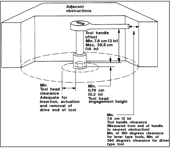
Notes:
Minimum tool head clearance must be adequate for insertion, actuation, and
removal of drive end of tool. Minimum 0.76 cm (0.3 in) tool head
engagement height. Tool handle offset minimum 7.6 cm (3 in), maximum 35.5
cm (14 in). Minimum 7.6 cm (3 in) tool handle clearance (measured from end
of handle to nearest obstruction). Minimum of 180 degrees clearance for
lever type tools. Minimum of 360 degrees clearance for driver type tool.
|
Reference: 1, Fig 36-1, p. 3/6-4; 351;
320; NASA-STD-3000 326
d. Tethering - A means shall be provided on all tools for tethering the tool at all times to prevent inadvertent loss. The design shall be such that the attachment and removal methods permit one-handed operation using pressure suit glove.
e. Battery-Powered Tools - Battery -powered tools shall:
1. support EVA translation with battery packs.
2. provide glove clearances for EVA removal and installation of batteries.
3. protect against safety hazards during EVA removal and installation of batteries.
4. restrain all fasteners used during battery replacement
5. support tethering of tool and batteries.
f. Battery Packs - Battery powered tools shall be designed so that the battery packs can be replaced at the EVA worksite. Power tools using battery packs shall have a level of charge indicator or an indication as to when a battery pack is required to be replaced.
g. EVA Tool Clearance - EVA tool head clearance requirements are defined in
Figure 14.6.2.3-1, except when fasteners are released using a robotic interface.
14.6.2.4 Example EVA Tools Design Solutions
{OP}
14.6.2.4.1 Example EVA Hand Tool Design Solutions
{A}
Past EVA tool design solutions have ranged from common tools modified for EVA tasks to specialized tools designed for mission-specific tasks.
An example of a tool designed specifically for EVA is an oversized 3/8-inch-drive ratchet. This wrench allows 360 degree ratcheting in either direction with a lever for selection of direction. The tool is equipped with a palm wheel that is turned by hand when over-torquing needs to be avoided, or when resistance is insufficient to operate the ratchet or when used as a speed wrench. The handle is grooved to improve grip and has a tether ring at the end. An illustration of this wrench, along with dimensions and technical information, are given in
Figure 14.6.2.4.1-1.
Figure
14.6.2.4.1-1 STS EVA Ratchet Wrench as an Example Design Solution
to EVA Tool Design Requirements
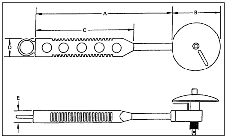 |
| Technical Information |
| Part number |
ESEX-82-27-10/ILC 10181-10023-01 |
| Weight |
0.63 kg (1.38 lb) |
| Material / construction |
Aluminum, tether ring on handle
Grooved handle with holes |
| Temperature |
-73 deg to 93 deg C
(-100 deg to 200 deg F) |
| Dimensional data |
| A |
26.04 cm
(10.24 in) |
| B |
8.89 cm
(3.50 in) |
| C |
15.24 cm
(6.00 in) |
| D |
3.81 cm
(6.00 in) |
| E |
1.91 cm
(0.75 in) |
|
Reference: 145, p. 3-10; NASA-STD-3000 327
14.6.2.4.2 Example EVA Power Tool Design Solutions
{OP}
The shuttle EVA power tool is a battery-powered, two-sped, variable torque unit with a 3/8 inch drive adapter fitting for attaching tools such as screwdrivers, sockets, and drill bits. Power is provided by a 7.2 Volt NiCd rechargeable battery that fits into the tool handle. The EVA power tool may be used for EVA tasks that require a tool to make many revolutions with variable speed and torque settings. The EVA power tool is shown in
Figure 14.6.2.4.2-1.
 |
| Technical Information |
| Part number |
10172-20500-01 |
| Weight |
1.24 kb (2.74 lb) |
| Material / construction |
Case - glass-filled lexan body, polyimide gear
housing covered with reflective aluminum tape
Battery pack - 7.2 V NiCd |
| Speed |
58 rpm, 101 rpm |
| Direction |
Forward/reverse (tighten/loosen) |
| Capacity |
375 to 450 screws/battery pack |
| Torque control value N-m (in-lb) |
| Speed |
Position |
Tighten |
Loosen |
| N-m |
(in-lb) |
N-m |
(in-lb) |
| 58 rpm |
1 |
106 |
(15) |
106 |
(15) |
| 2 |
205 |
(29) |
191 |
(27) |
| 3 |
381 |
(54) |
282 |
(40)
|
| 4 |
1172 |
(166) |
1059 |
(150)
|
| 101 rpm |
1 |
71 |
(10) |
85 |
(12)
|
|
2 |
184 |
(28) |
141 |
(20)
|
|
3 |
290 |
(41) |
240 |
(34)
|
|
4 |
1358 |
(192) |
1236 |
(175)
|
|
| Dimensional data |
| A |
26.04 cm
(10.24 in) |
| B |
8.89 cm
(3.50 in) |
|
Reference: 145, p. 3-6; NASA-STD-3000 328
14.6.3 EVA Fasteners
{A}
{A}
This section provides EVA fastener design considerations and requirements.
(Refer to Paragraph 11.9, Fasteners, for fastener design considerations and requirements that may be applicable to both IVA and EVA.)
14.6.3.2 EVA Fasteners Design Considerations
{A}
EVA fasteners should be selected based on hardware structural requirements and the following EVA considerations:
a. Glove Interface - Fasteners should be designed for use with pressurized gloves for on-orbit operations versus bare-hand actuation during ground operations.
b. Hand-Actuated Fasteners - Hand-actuated attach systems (including knobs, levers, latches, rings, clamps), if used for EVA ORU design, should be in compliance with those imposed on IVA hand-actuated fasteners.
c. Dexterity and Torquing Capabilities - Actuation of fasteners during EVA is accomplished by a crewmember in a pressurized suit. Pressure suit gloves reduce the dexterity and torquing capabilities compared to bare hand capability.
d. Visual Accessibility - EVA actuated fasteners/ devices should be visually accessible to ensure proper seating or restraint in stowed or installed location.
e. Size - Large fasteners and knobs up to 5.1 cm (2 in) diameter are easier to operate with a pressurized gloved-hand. The inability of the crewmember to feel the fasteners makes them more difficult to grip and use.
f. Captive/Noncaptive Fasteners - Tool-operated fasteners (captive and noncaptive) used on space module equipment should have the sacrificial portions of a fastener attached to the ORU side of the interface.
g. Torque Tip - Torque set, recessed, Phillips, and slotted-type fasteners should not be used.
h. Sizes - Minimize different sizes of fasteners and variation of drive depths.
i. Locks - Use self-locking feature on all fasteners.
(Refer to Paragraph 11.9.2, Fastener Design Considerations, for other considerations that pertain to fasteners.)
14.6.3.3 EVA Fasteners Design Requirements
{A}
The following requirements pertain to EVA fasteners:
a. EVA Fastener Size - The minimum size of fasteners, knobs, and head size for space-suited hand operation shall be 3.8 cm (1.5 in.) diameter and 1.9 cm (0.75 in.) high. Maximum EVA fastener size shall not exceed the grasp capabilities of the smallest EVA crewmember.
b. Captive - Captive fasteners shall be used wherever possible. Where existing hardware or other factors preclude captive fasteners, special provisions for captive devices shall be made.
c. Indication of Status - EVA actuated fasteners/devices shall be verifiable/visually accessible to ensure proper seating or restraint in stowed or installed locations.
d. Contingency Operation - All EVA hand-actuated rotational fasteners shall be provided with either an internal or external hexagonal feature for contingency operation with a hand tool.
e. Fastener Heads - EVA-operable bolt fasteners shall not require a push force to remain engaged with tool. EVA fasteners operated by hand or power tool shall have a double-height Hex-head bolt head.
(Refer to Paragraph 11.9.3, Fastener Design Requirements, for additional requirements.)
f. Cotter Keys - Cotter keys shall not be used EVA.
14.6.4 EVA Connectors
{A}
{A}
This section provides EVA connector design considerations and requirements.
(Refer to Paragraph 11.10, Connectors, and sub- paragraphs for connector design considerations and requirements).
14.6.4.2 EVA Connectors Design Considerations
{A}
EVA connectors should be designed based on the following:
a. Clearance - Sufficient clearance should be allowed around the connector for access by a space suit gloved hand. Otherwise, additional provisions should be made to access connector.
b. Mate/Demate - Design limits should be placed on the torque required to mate/demate connectors, and connector type and spacing.
(Refer to Paragraph 11.10.2, Connector Design Considerations, for additional considerations.)
14.6.4.3 EVA Connectors Design Requirements
{A}
The following requirements pertain to EVA connectors:
a. Clearance - Clearance shall be provided for gloved- hand operation of connectors as shown in
Figure 14.6.4.3-1.
Figure 14.6.4.3-1
Typical EVA Gloved Hand Clearances Required for Wing Tab Connectors
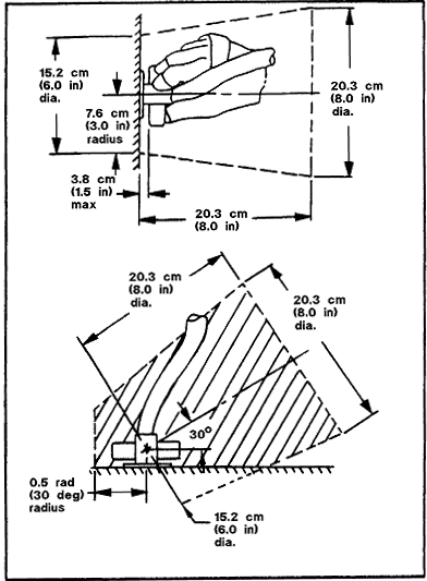
Reference: 253, Fig. 2.4-4, p. 2-6; 320
NASA-STD-3000 329
b. Wing Connectors - EVA wing connectors, similar to Figure
14.6.4.3-2, shall be used wherever appropriate. Wing length shall be proportional to the torque required.
c. Multiple Connectors - Clearance between single and staggered rows of connectors shall be at least 3.8 cm (1.5 in.) as shown in
Figure 14.6.4.3-3.
d. Pressure - Pressurized pneumatic connectors and lines shall be tethered or otherwise captured to the main structure.
d. Spacing - Spacing of connectors shall allow the gloved hand access to the connector in all directions.
e. Status - Methods such as visual indications, shall be provided to indicate connector mating status.
f. Pressure - Pressurized pneumatic connectors and lines shall be tethered or otherwise captured to the main structure.
g. Protecting Caps - All connector protective caps shall be tethered in the proximity of the connector.
h. Strain Relief - Strain relief shall be provided to prevent inadvertent breakage due to induced loads.
i. Alignment - All connectors shall have provisions to ensure proper alignment during mating and demating and visible alignment markings.
j. Scoop Proof - All connectors shall be scoop proof. Scoop Proof refers to the impossibility of a mating receptacle connector being inadvertently cocked into a mating plug and damaging or electrically shorting the contacts.
k. Mate/Demate - The actuation force to mate or demate an electrical or fluid connector shall not exceed 4 Nm (35 in/lb) for the preferred diameter of 5.75 cm (2.25 in.) for connectors.
l. Electrical Hazards - All electrical connectors shall have provisions for alignment and mating of connector shells prior to electrical path connections. Electrical paths shall be broken prior to connector disconnections.
(Refer to Paragraph 11.10.3, Connector Design Requirements, for additional information applicable to both EVA and IVA connectors.)
Figure 14.6.4.3-2
EVA Wing Tab Connector (Large Size)
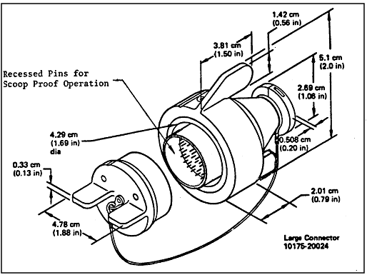
Reference: 320; NASA-STD-3000 330
Figure 14.6.4.3-3
Minimum Clearance Between Wing Tab Connectors
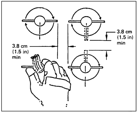
Reference: 253, Figure 2.4-2, p. 2-5; NASA-STD-3000 331
14.7 EVA ENHANCEMENT SYSTEMS
{A}
14.7.1 Introduction
{A}
This section provides basic guidelines for EVA enhancement systems. Enhancement systems in this context are defined as specialized equipment or systems used to aid the EVA crewmembers in the performance of their tasks. Examples of STS EVA enhancement systems are also included in this section.
14.7.2 EVA Enhancement Systems Design Considerations
{A}
EVA enhancement systems are specialized systems or equipment designed to aid the EVA crewmembers in the performance of their tasks. For example, the Orbiter's remote manipulator arm with the MFR, and the manned maneuvering unit are STS EVA enhancement systems.
When appropriate, crew aids such as handrails, handholds, tethering devices, and foot restraints should be incorporated into the design of EVA enhancement systems.
EVA enhancement equipment should incorporate mounting interface design features compatible with crew-imposed loads resulting from inadvertent impact and/or from the operation of crew aids.
14.7.3 EVA Enhancement Systems Design Requirements
{A}
EVA Enhancement systems shall have safety tether attachments between the EVA crewmember and the enhancement system and or between the enhancement and the main space module, except for free-flying mobility units or surface rover.
14.7.4 EVA Enhancement Systems Example Design Solutions
{A}
Example design solutions for STS EVA enhancement systems are given in this section.
14.7.4.1 Manned Maneuvering Unit (MMU)
{A}
The MMU is a modular self-supporting backpack, containing its own electrical power, propulsion system, and controls. It readily attaches to the EMU and can be donned, doffed, and serviced by one EVA crewmember for use as required during a nominal EVA. It has complete 6-DOF (degrees of freedom) control and automatic attitude hold capability. It provides attachment points for the use of ancillary equipment.
The MMU is used to increase the EVA crewmember's mobility to other portions of the space module, to appendages of payloads protruding from the cargo bay, or to other space modules. It can be modified to carry cargo of moderate size, to stabilize satellites, to retrieve small free-flying payloads, and to provide remote inspection photography/television of operations. MMU dimensions and technical data are provided in
Figure 14.7.4.1-1.
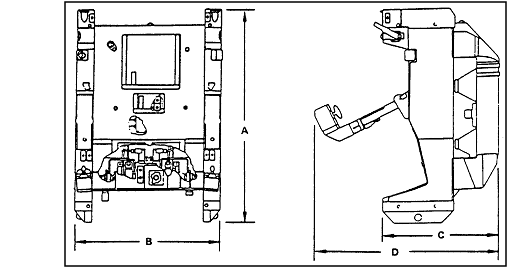 |
| Technical Information |
| Part number |
852MU000000 |
| Weight |
153 kb (338 lb) |
| Material |
Aluminum |
| Control |
Three modes of operations - normal, satellite
stabilization, and axis inhibit.
Automatic attitude hold is available in all three modes
Left hand controller - 3ODF translation
Right hand controller - 3DOF rotation
Translation acceleration - approximately 0.07 to 0.11 m/sec2
(0.24 to 36 ft/sec2)
Rotational acceleration - 6 to 14 deg/sec2
Redundant logic |
| Maximum range |
Early flights - approximately 91 m (300 ft)
Potential - approximately 914 m (3000 ft) |
| Electrical power |
Two batteries: total power 852 W-hr |
| Propellant |
Gaseous nitrogen 12 kg at 20,680 Kp (26 lb at
3000 psig)
Reservicing in less than 10 min |
| Stowage |
Forward cargo bay (bay 1) in its own FSS |
| Dimensional data |
| A |
127.0 cm
(50.0 in) |
| B |
84.6 cm
(33.3 in) |
| C |
68.6 cm
(27.0 in) |
| D |
121.9 cm
(48.0 in) |
|
Reference: 145, p. M-4; 320;
NASA-STD-3000 332
The following design considerations are for any EVA manned maneuvering system.
a. The manned maneuvering vehicle should accommodate the full range of space suit sizes.
b. Six degrees-of-freedom of simultaneous maneuvering capability is required in any combination of axes.
c. The acceleration levels provided by the maneuvering vehicle must be compatible with mission requirements and crew comfort levels.
d. Automatic attitude hold is required to allow the pilot to maintain a fixed position in the rotational axes.
e. The vehicle design shall minimize crew time to operate the MMU systems while accommodating the pressure suit design.
14.7.4.2 Remote Manipulator System (RMS)
{O}
The STS RMS, as an available orbiter payload standard service, is mounted on the portside of the Orbiter cargo bay. The arm length from the shoulder is 50 feet, and 6 degrees of manipulator freedom are provided through joints at the shoulder, elbow, and wrist. A second RMS can be mounted on the starboard side.
The RMS has been used as a Shuttle support system in satellite servicing.
RMS capabilities include:
a. Deploying and releasing payloads.
b. Capturing and retrieving non spinning satellites through mechanical interface.
c. Supporting space module servicing by maneuvering crewmembers and positioning workstations, and transferring equipment.
d. Handling modules unsuitable for crewmember handling (size, inertia, radioactive, etc.).
e. Use in remote servicing.
The RMS television camera and light located near the end effector can be used to enhance EVA capabilities.
14.7.4.3 Manipulator Foot Restraint (MFR)
{O}
The MFR is a crewmember restraint device and work- station which is grappled by the remote manipulator system. The MFR provides translation, positioning, and restraint in cargo bay worksites within reach of the RMS for EVA crewmembers. Positioning of the MFR is by voice link with the RMS operator in the cabin. A safety tether is attached to the foot restraint platform for crewmember use. Several parts of the MFR rotate to provide a wide range of crewmember motion.
The MFR also provides for tool stowage. Tool stowage consists of a standard interface for a tool board on which a variety of hand tools or parts can be attached.
Figure 14.7.4.3-1 provides the MFR dimensions and technical data.
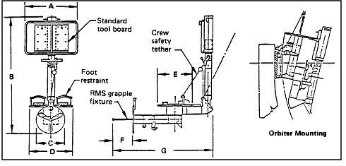 |
| Technical Information |
| Part number |
SED33103150-305 |
| Weight |
46 kg (102 lb) |
| Material |
Primarily aluminum |
| Rotation of MFR base including vertical
stanchion |
± 180 deg with locking in 45 deg increments |
| Tilt of stanchion away from crew member |
27 deg forward with locking in 9 deg increments |
| Rotation of workstation about vertical
stanchion axis |
± 180 deg with locking in 45 deg
increments
|
| Rotation of foot platform independent of base |
Continuous 360 deg with locking in 30 deg
increments |
| Stowage |
Cargo bay, attached to APC |
| Dimensional data |
| A |
63.5 cm
(25.0 in) |
| B |
156.2 cm
(61.5 in) |
| C |
35.6 cm
(14.0 in) |
| D |
52.1 cm
(20.5 in) |
| E |
36.8 cm
(14.5 in) |
| F |
20.3 cm
(8.0 in) |
| G |
133.4 cm
(52.5 in) |
|
Reference: 145, p. M-2; NASA-STD-3000 333
Return to Volume I Home


