Volume I, Section 11
11 HARDWARE AND EQUIPMENT
{A} For a description of the notations, see Acceleration
Regimes.
This section contains the following topics:
11.1 Introduction
11.2 Tools
11.3 Drawers and Racks
11.4 Closures and Covers
11.5 Mounting Hardware
11.6 Handles and Grasp
Areas
11.7 Restraints
11.8 Mobility Aids
11.9 Fasteners
11.10 Connectors
11.11 Windows
11.12 Packaging
11.13 Crew Personal Equipment
11.14 Cable Management
See the video clips
associated with this section.
{A}
This section provides the design considerations, requirements, and
examples for the following hardware and equipment: Tools, Drawers and
Racks, Closures and Covers, Mounting Hardware, Handles and Grasp Areas,
Restraints, Mobility Aids, Fasteners, Connectors, Windows, Packaging,
Crew Personal Equipment, and Cable Management.
11.2 TOOLS
{A}
11.2.1 Introduction
{A}
This section includes the criteria for manual and power tools. It provides
tool design requirements for normal operations and for planned and unplanned/contingency
maintenance activities. Launch, entry, and temporary tool stowage requirements
are also included along with examples of tool design solutions
(Refer to Paragraph 14.6.2, EVA
Tools, for EVA-unique tool considerations and requirements.)
(Refer to Paragraph 12.3.2, Testability
Design Requirements for information relevant to electronic and analytical
test tools.)
11.2.2 Tool Design Considerations
{A}
Development of in-flight maintainable spacecraft systems must include
consideration of tool selection, transport, stowage, ease of use, and
criticality.
A satisfactory tool complement for future missions should include consideration
of the following factors:
a. Tool Kit Contents - A tool kit should contain all the tools normally
found in a tool collection for comprehensive usage as well as special
tools required for special aerospace hardware. A standard tool kit should
be developed that is based on known system requirements as well as past
experience. This tool kit should include multi-purpose/multi-size tools.
Despite the urge to reduce tool kit weight by not including sockets,
wrenches, etc., that have no identified requirements, crewmembers have
requested that all sizes be included as there are always unexpected
needs that arise for the tool that was left behind.
b. Tool Transfer/Retention Device - A tool caddy should be provided
to carry/translate tools from place to place and should be easily secured
at the workstation. Transparent materials would be desirable so that
the tools can be seen inside the caddy. Internal retention provisions
are necessary to allow the crewmember to temporarily stow and retrieve
small parts and equipment while the work is being done since containing
and locating this equipment is a problem in microgravity.
c. Tool Commonality/Cost-effectiveness - A survey of previous tool
development activities should be conducted prior to initiating costly
tool development for suitable tools that are already in the inventory.
d. Tool Stowage Location - The stowage location of tool kits should
be optimized for accessibility to workstations and maintenance workbenches.
e. Tool Unit Standards - Both English and metric standards must be
accommodated in the tool kits. Some coding system on the tool should
be used to readily distinguish English from metric.
f. Tool Inventory Control - Tools should be identifiable by the automated
inventory control system.
(Refer to Paragraph
13.3, Inventory Control for specific inventory control design considerations
and requirements.)
11.2.2.1 Power Tools
Design Considerations
{A}
Power tools must meet the same design requirements as manual hand-tools
regarding operability. Power tools should be used to accomplish repetitive
manual tasks, such as disengaging captive fasteners or operating mechanical
drive systems. Use of power tools offers enormous returns in reduced
crewmember time and effort and ease of operation.
(See Paragraph 14.6.2, EVA Tools,
for design considerations pertaining to power tools used in an EVA environment.)
Power tools subject the crewmember to specific hazards and stresses
that should be considered. Specific considerations include rotating
components, electrical shock, heat generation, flying particles or sparks,
inadvertent power activation, and hazards to the nonoperating hand.
Power tool design should avoid the use of brush type motors since they
may create hazardous EMI (electromagnetic interference) and provide
an ignition source.
(Refer to Paragraph
6.4, Electrical Hazards, for electrical safety design considerations
and requirements.)
Some types of tools create unique problems. Typical of these are soldering
tools, which can cause burns if the operator touches a tip that is still
hot or lays the tool on flammable materials.
It should be noted that the standard practice has been to accept many
of the above hazards as part of the job and to place the burden of protection
on users, i.e., to recommend wearing eye protectors, using special electrical
grounding devices, wearing gloves, etc. In many cases these are the
only methods available to reduce the hazard potential. However, the
designer should, in each new tool design, review such hazards and attempt
to remove them whenever possible in the design. When this cannot be
accomplished, the designer should assume the responsibility for providing
appropriate warning labels on the tool and/or include properly worded
warning instructional materials with the tool. The designer should know
better than anyone else what hazards a new tool presents.
(Refer to Paragraph 6.2,
General Safety, for more detailed safety design considerations.)
For rechargeable battery-powered tools, the inventory of spare power
packs and the location of recharge stations are important design considerations.
11.2.2.2 Body Stabilization
When Using Tool Design Consideration
{A}
Previous orbital missions have indicated that, when properly restrained,
the crewmembers can perform most manipulative operations on orbit using
standard tools as effectively as these operations can be performed in
an Earth environment. In many in-space maintenance operations, this
adequate restraint was not anticipated in the design of the equipment.
This led to a lot of wasted time and crew frustration. Therefore, it
is very important that adequate interface designs (i.e., designing the
payload for EVA and IVA servicing), adequate body restraints, and a
moderate complement of hand tools be provided so space system servicing
requirements can be met.
(Refer to Section 12.0, Design for Maintainability,
for general and specific requirements for designing payloads for servicing.)
(Refer to Paragraph 9.2.4.2.3,
Workstation Restraints and Mobility Aids, and to
Paragraph 14.4.3, EVA Workstations and Restraints, for specific
requirements related to integrating restraints and workstations.)
11.2.3 Tool Design Requirements
{A}
The tool design requirements in the following subsections apply to
tools that are intended to be used to activate, operate, maintain, and
deactivate manned and unmanned equipment in both EVA and IVA environments.
(Where there are EVA-unique tool design requirements, they are so noted
with reference to Section 14.0.)
11.2.3.1 Hand and
Tool Integration Design Requirements
{A}
11.2.3.1.1 Tool
Handgrip Size and Shape Design Requirements
{A}
Power and manual hand tools shall comply with the following handgrip
size and shape requirements:
(Refer to Paragraph 6.5.3, Touch
Temperature Design Requirements for specific touch temperature criteria.)
a. Gripping Surface - Hand gripping surfaces that minimize abrasion
to the EVA glove material shall be provided on handles of tools.
b. Sleeve Type Adapters - If sleeve-type handle cover adaptors are
used, they shall be adequately secured so they will not slip, rotate,
or come off.
c. Orientation - Tool handles shall be oriented to allow the operator's
wrist to remain in the most natural position while force or guidance
inputs are applies.
d. Auxiliary Controls - If an auxiliary control on the tool must be
manipulated while the operator is holding the tool, the control shall
be located where:
1. The thumb or finger of the holding hand can manipulate the control
without disturbing the tool/fastener holding position.
2. Unintentional or inadvertent control operation is impossible.
11.2.3.1.2 Tool
Handedness Design Requirements
{A}
The following requirements apply to handheld manual tools and handheld
power tools:
a. Tool Operation - All general purpose hand tools shall be one-handed
operable insofar as practical.
b. Tool Installation/Alignment - One hand only shall be required for
tool installation and alignment.
c. Tool Handle Design - Tool handles shall be designed to allow the
operator to use either the left or right hand.
11.2.3.1.3
Tool Actuation Forces and Direction of Action Design Requirements
{A}
All hand tools shall comply with the following:
a. Actuation Force - Hand tools shall require an actuation force of
less than 89N (20 lbs.) or a torque of less than 15 Nm (11 ft-lbs).
b. Throw Angles - Ratcheting tools shall be capable of providing torque
with a minimum throw angle of 45 degrees.
c. Plier-Type Tools - Plier-type tools shall be spring-actuated in
the open direction to permit one-handed operation.
d. Driver-Type Tools - Driver-type hand tools shall not require a push
force to maintain tool engagement while providing torque.
11.2.3.2 Tool Commonalty
Design Requirements
{A}
To ensure that the tool complement is kept at a minimum, the following
requirements shall apply:
a. Tool Quantity - The number of different types of tools shall be
minimized.
b. Standard Attaching Hardware and Fasteners - Size and type of attaching
hardware and fastener head configurations shall be standardized throughout
the vehicles to limit the number and kind of tools required to perform
maintenance tasks.
(Refer to Paragraph 11.9, Fastener
Design Requirements, for specific fastener-to-tool interface requirements.)
c. Special Tools - The number of different and special tools required
for maintenance shall be minimized.
d. For every
type and size of fastener used onboard, a corresponding tool(s) shall
be available for removal/replacement.
(Refer to Paragraph 11.9.3.1, Fastener Design
Requirements for specific considerations and requirements).
11.2.3.3 Tool Tethering/Retention
Design Requirements
{A}
The following tool tethering and tool retention requirements shall
be apply:
a. Tool Restraints - A means shall be provided on all tools for restraining
the tool during use.
b. Tool Transporter Devices - Tool carriers shall be provided to transport
tools and to retain these tools during the maintenance activity.
c. Retention of Small Parts - Tool carriers/transfer devices shall
provide a means of retaining small parts and attaching hardware. Items
retainable in this manner shall be visible for retrieval.
d. Tool Restraint During Translation - Tools shall be restrained in
the tool carrier/transfer device with sufficient force to prohibit detachment
during translation.
e. Tool Carrier Attachment - Tool carriers and tool retention devices
shall have provisions to attach the device to the crewmember or to adjacent
structure or equipment.
(See Paragraph 11.7.3.3, Equipment Restraint
Design Requirements, for other applicable restraint requirements.)
f. Inadvertent Tool Disassembly - A means shall be provided to prevent
inadvertent tool disassembly while installing, using, removing, or transporting
the tool.
11.2.3.4 Tool Stowage
Design Requirements
{A}
Tool stowage must allow for ease of retrieval, retention, identification,
and replacement. To accomplish this, the following requirements shall
apply:
a. General - A systematic approach shall be used in stowing tools and
maintenance aids throughout the space module.
b. Stowage Provisions - Provisions for launch, entry, and temporary
in-flight stowage shall be provided.
c. Stowage Location:
1. Specialized tools shall be stowed in areas which correspond to their
functional applications.
2. All general-purpose tools shall be grouped in one specific area.
d. Tool Stowage List - A tool summary or listing of the entire tool
inventory, including stowage locations, shall be available onboard the
space module.
e. Tool Arrangement in Stowage Container - A systematic approach shall
be used in the arrangement of tools in the tool kit.
f. Temporary Stowage at Work Area - A systematic approach and a methodical
layout of tools at the work area shall be required.
(Refer to Paragraph 10.12.3, Stowage
Design Requirements, for other specific stowage requirements.)
11.2.3.5 Tool Labeling
and Identification Design Requirements
{A}
Tool and tool stowage labeling and identification requirements shall
comply with the following:
(Refer to Paragraph 9.5.3, Labeling
and Coding Design Requirements for detailed labeling and coding requirements.)
a. Selection of Names for General Tools - Tool names shall be identical
to those names called out on the tool/ tool label and, in all cases,
will be the most common definitive name recognizable by the crewmembers.
b. Selection of Names for Specialized Tools - Specialized tool nomenclature
shall describe the specific task it is intended to accomplish and shall
not be identified with the equipment it is servicing.
c. Identification of Specialized Tools - When special tools are absolutely
necessary, they shall be coded and/or marked to indicate intended use.
d. Tool Labels - Prominent labels shall be provided adjacent to each
tool in the stowage container/kit if the tool is not readily recognizable.
e. Tool Metric/English Identification - All tools shall be labeled
or coded to indicate whether the tool is sized in metric or English
units.
f. Tool Inventory Control Labeling - Tools shall be tracked by an automated
inventory control identification system.
(Refer to Paragraph 13.3.3, Inventory
Control Design Requirements, for specific requirements.)
g. EVA Tool Compatibility - IVA tools that are EVA compatible shall
be so identified.
11.2.3.6 Tool Access
Design Requirements
{A}
The following tool access volume and operational constraints requirements
are applicable to both IVA and EVA hardware design (refer to
Figure 11.2.3.6-1 for IVA requirements and
Paragraph 14.6.2.3 for EVA requirements):
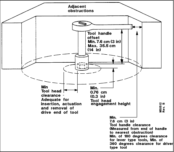
Notes:
Minimum tool head clearance must be adequate for insertion, actuation,
and removal of drive end of tool. Minimum 0.76 cm (0.3 in) tool
head engagement height. Tool handle offset minimum 7.6 cm (3 in),
maximum 35.5 cm (14 in). Minimum 7.6 cm (3 in) tool handle clearance
(measured from end of handle to nearest obstruction). Minimum
of 180 degrees clearance for lever type tools. Minimum of 360
degrees clearance for driver type tool.
See Figure 14.6.2.3-1
for EVA requirements. |
Reference: 320; NASA-STD-3000
12b
a. Tool Head Clearance - Where only tool access is required, clearance
shall be provided around the fastener or drive stud for insertion, actuation,
and removal of the drive end of the tool.
b. Tool Handle Clearance - A minimum of 7.6 cm (3 in.) shall be provided
for clearance between a tool handle engaged on a fastener or drive stud
and the nearest piece of hardware. The tool handle should be able to
maintain this clearance through a full 180 deg. swept envelope.
c. Tool Head-to-Fastener Engagement Height - The tool socket/fastener
head engagement height shall be sufficient to lower the bearing loads
on the fasteners and tool below the failure limits of the materials.
d. Tool Handle Offset - The maximum tool offset between the tool handle
and the tool head shall be 35.5 cm (14 in.).
e. Access for Tools - Minimum tool access clearance for hand tool actuation
is given in Figure 11.2.3.6-2.
Figure
11.2.3.6-2 Minimal Clearance for Tool-Operated Fasteners
| Opening dimensions |
Task |
.gif) |
A 117 mm (4.6 in)
B 107 mm (4.2 in) |
Using common screw-driver with freedom to turn hand through 180° |
.gif) |
A 133 mm (5.2 in)
B 115 mm (4.5 in) |
Using pliers and similar tools |
.gif) |
A 117 mm (6.1 in)
B 107 mm (5.3 in) |
Using T-handle wrench with freedom to turn wrench through 180°
|
.gif) |
A 203 mm (8.0 in)
B 135 mm (5.3 in) |
Using open-end wrench with freedom to turn wrench through 62°
|
.gif) |
A 122 mm (4.8 in)
B 155 mm (6.1 in) |
Using Allen-type wrench with freedom to turn wrench through 62°
|
| Notes:
1. Refer to Figure
12.3.1.2-1 for other hand and arm access hold dimensions.
2. Refer to Figure 11.2.3.6-1. |
Reference: 1, p. 4.4-7;
NASA-STD-3000 27
11.2.3.7 Special Tool Features Design Requirements
{A}
Compliance with the following special features shall be required when
designing or providing tools for IVA servicing and maintenance tasks:
a. Non-sparking Tools - Non-sparking materials shall be required for
general purpose tools.
b. Nonconductive Tools :
Refer to Paragraph 6.5.2, Touch
Temperature Design Requirements, when tools are to be used in extremely
hot or cold temperature areas.)
(Refer to Paragraph 6.4.3, Electrical
Hazards Design Requirements, for requirements for insulation protection
against electrical hazards.)
c. Finish - Tools shall be capable of being refinished in flight in
order to remove burrs.
(Refer to Paragraph 6.3.3, Mechanical
Hazards Design Requirements, for burrs, corners, edges, and protrusion
design requirements.)
d. Battery Pack :
1. Power tools shall be designed so the battery packs can be replaced
at the worksite.
2. Power tools using battery packs shall have a level-of-charge indicator
or an indication as to when a battery pack is required to be replaced
or recharged.
3. Hazards associated with charging and stowage of rechargeable batteries
(such as toxic or flammable offgassing, leakage of corrosive electrolytes
or high temperatures) shall be addressed and controlled.
11.2.4 Example Tool Design Solutions
{A}
Examples of previously used IVA tools are included in this section
to illustrate how tools are constructed, stored, identified, transferred,
tethered, or restrained at work locations. These proven examples should
be considered when developing new tools and maintenance aids for future
missions.
(Refer to Paragraph 14.6.2.4,
Example EVA Tools Design Solutions, for description of EVA tools.)
11.2.4.1 Example Manual Tools
{A}
The following IVA tools have flown successfully on STS missions:
(Refer to Reference 150 for complete details on STS tools.)
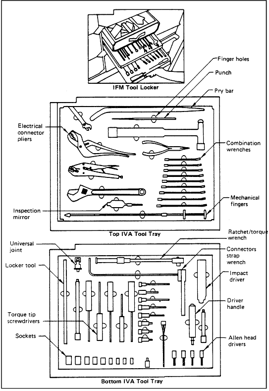
a. Off-the-Shelf STS IVA Tools - Examples of off-the- shelf IVA tools,
stowage, and identification methods are shown in
Figure 11.2.4.1-1, Figure 11.2.4.1-2
and Figure 11.2.4.1-3.
b. Stowage Provisions - Stowage provisions are shown in
Figure 11.2.4.1-1, Figure 11.2.4.1-2
and Figure 11.2.4.1-3. Tool trays
include provisions for individual hand tools in the trays by providing
cushions fabricated from white foam with a fine cell structure. Very
accurate cuts were required to provide adequate retention for launch,
in-flight, and enter environments. Tools were individually identified
at each location. The foam is coated with a fire-retardant seal material.
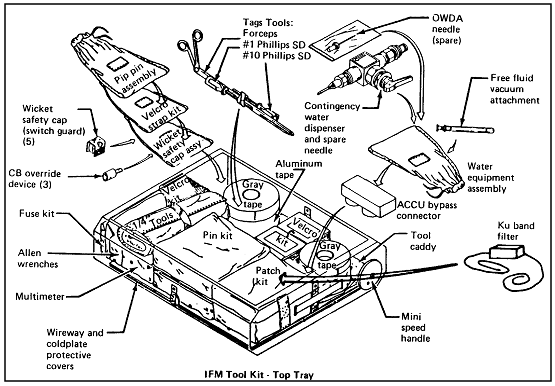
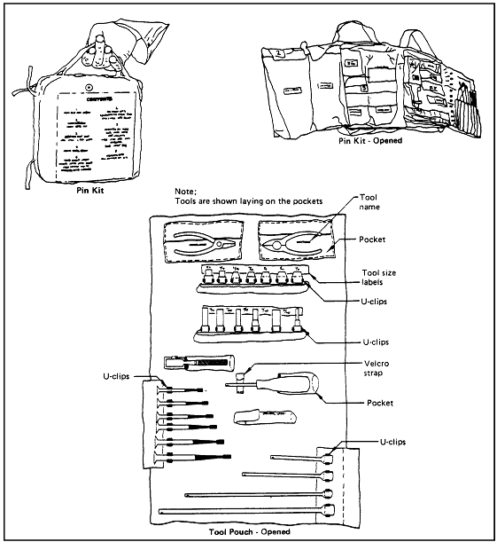
c. Tool Kits and Tool Pouches - Tool kits and tool pouches (Figure
11.2.4.1-3) were used to retain small tool packages to worksites.
These kits or pouches had provisions (snaps, straps, Velcro, etc.) for
attaching the units to the worksite structure.
Figure
11.2.4.1-1 Examples of IVA Hand Tools, Stowage, and Identification
Reference: 150, p. 3.23-10;
NASA-STD-3000 13
Figure
11.2.4.1-2 Miscellaneous IVA Tool Stowage Examples
Reference: 150, p. 3.23-14;
NASA-STD-3000 14
Figure
11.2.4.1-3 Tool Translation and Retention Pouch Examples
Reference: 150, p. 3.23-16
and -18; NASA-STD-3000 15
11.2.4.2 Example Power Tools
{A}
The vacuum cleaner is an example of an IVA power tool used on Skylab,
Shuttle and Spacelab missions. The vacuum cleaner is a tool which is
presently used for cleaning intake screens to black box cooling fans,
orbiter air filters, and Spacelab Environmental Control System (ECS)
filters. The unit is also used for general housekeeping chores.
(Refer to Paragraph 13.2
Housekeeping, for housekeeping design considerations and requirements.)
Another example of IVA power tools is the EVA Power Tool utilized to
remove panel fasteners in an IVA mode.
(Refer to Paragraph 14.6.2.4.2,
Example EVA Power Tool Design Solutions, for a description of this STS
EVA power tool.)
11.3
DRAWERS AND RACKS
{A}
11.3.1 Introduction
{A}
This section provides the design considerations and requirements for
drawers and racks. This includes the definition of size, interfaces,
operating mechanisms, location relative to workstations and traffic
patterns, ease of use, restraints, and utility connections.
Stowage drawers are a specific type of stowage compartment.
(Refer to Paragraph
10.12, Stowage Facility for general and specific stowage design
considerations and requirements that are also applicable to drawers.)
Equipment drawers are a specific type of equipment mounting hardware
that are designed to facilitate equipment replacement and maintenance.
(Refer to Section 12.0, Design for Maintainability,
for general and specific maintainability design considerations and requirements
that are also applicable to equipment drawers.)
11.3.2 Drawer and Rack Design Considerations
{A}
There are two types of drawers that are used in space modules: storage
drawers and equipment drawers. Stowage drawers and equipment drawers
are similar in that both are mounted in racks, cabinets, or housings;
they are designed to slide out to provide the user with access to their
contents; they stay in the open position until pushed back into the
stowed position; and they can be removed from the housing/cabinet by
some secondary unlatching operation. They are distinguished from each
other by the fact that stowage drawers are used to stow normally removable
contents, whereas equipment drawers are used to mount subsystem components.
The contents of a stowage drawer can be removed or replaced easily as
the contents are restrained by soft restraints (e.g., foam cutouts,
elastic bungee cords, etc.) which can be easily manipulated by hand
without using any tools. The contents of an equipment drawer, on the
other hand, usually need to be removed or replaced using a hand tool.
Equipment drawers always have utility connections(such as power and
thermal control), whereas stowage drawers generally have none.
Because of their similarities, stowage and equipment drawers need to
be designed with many of the same design considerations and requirements.
The drawer becomes a workstation when the crewmember has a need to
access its contents. This requires adequate crewmember restraint while
using it, handles and latches that are designed for one-handed operation,
ease of access to the contents, restraint of the drawer/rack in the
opened position, Commonalty with other drawers/racks, etc.
Racks are structural housings into which equipment drawers and other
types of equipment mounting hardware are installed. The racks are either
single-wide units (i.e., they are designed to mount a single stack of
equipment drawers) or they are double-wide units (i.e., they are designed
to mount a side-by-side stack of equipment drawers so they can house
a double-wide equipment drawer). The racks generally have built-in utility
(e.g., thermal, power, data) distribution systems which are designed
to provide interfaces with each of the installed equipment drawers.
The rack's utility system interfaces with the space module's utilities
distribution system at standardized locations.
In the closed position, drawers should be designed to contain particulates,
liquids, or gaseous matter. Drawer opening and closing mechanisms should
incorporate some form of motion damping to prevent disturbance of the
micro-g environment and to hold the drawer at intermediate positions
for zero-g operations. The use of magnetic latches on drawers and doors
should be avoided if at all possible
11.3.3 Drawer and Rack
Design Requirements
{A}
11.3.3.1 Drawer
and Rack Interfacing Requirements
{A}
Stowage drawers, equipment drawers and racks shall be designed to provide
the following interfacing features:
a. Size :
1. Unless prohibited by functional needs, all racks shall be designed
to house single-wide drawers (and other types of equipment mounting
hardware) that shall be 48.26 cm (19.00 in) wide or double-wide drawers
that shall be 96.52 cm (38.00 in) wide.
(Refer to Paragraph 2.3.2, Standardization
Design Requirements, for the general standardization requirements.)
2. If equipment is intended to be launched and returned in the Shuttle
stowage lockers, it shall be sized per
Figure 11.3.3.1-1.
b. Location Related to Traffic Patterns - Racks that require frequent
drawer deployment shall be located in areas that do not have high traffic.
(Refer to Paragraph 8.7.3, Traffic
Flow Design Requirements, for general and specific requirements related
to blocking traffic patterns.)
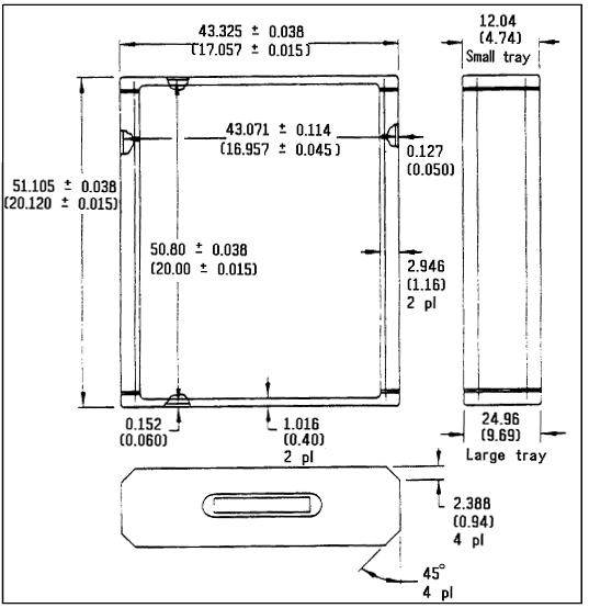
Note: Tolerances: 0.0002 cm (0.0001 in) Small tray; 0.0005 cm
(0.0002 in) Large tray |
Reference: 350, Figure
4 and 5; NASA-STD-3000 229
c. Unobstructed Volume for Use - Provide adequate clearance such that
the drawers can be opened, removed, and replaced without obstructions
from adjacent hardware.
d. Easily Removable - Rack and drawer interfaces shall be designed
such that the drawers can be removed from their rack or cabinet along
a continuous straight or slightly curved path without using tools.
e. Limit Stops:
1. Provide limit stops that will prevent the drawer from being unintentionally
pulled out of the rack.
2. The limit stops shall be designed to hold the drawer in the full
open position.
3. The limit stops shall be capable of being disengaged without using
a tool to enable drawer removal.
f. Drawer Movement Forces - Drawer opening/closing or removal/installation
shall not require a force greater than 156 N (35 lbs).
(Refer to Paragraph 4.9.3, Strength
- Design Requirements, for crewmember strength requirements.)
g. Alignment Guides - Provide guide pins or equivalent to aid in alignment
when replacing a drawer into its rack or cabinet.
(Refer to Paragraph 11.5.3.2, Alignment Devices
Design Requirements, for detailed requirements.)
h. Shuttle Compatibility - If equipment is intended to be launched/returned
within the Shuttle, it shall be designed for compatibility with the
Shuttle stowage system.
i. Stowage Trays
1. Provide limit stops that will prevent the tray form being unintentionally
pulled out of the drawer.
2. The limit stops shall be designed to hold the tray in the 3/4 open
position.
3. The limit stops shall be capable of being disengaged without using
a tool.
11.3.3.2 Design
Requirements Common to Both Stowage and Equipment Drawers
{A}
In addition to the requirements given in Paragraph
11.3.3.1, all stowage and equipment drawers shall be designed to
provide the following features:
a. Latches/Handles/Operating Mechanisms - All latches, handles, and
operating mechanisms shall be designed to be easily latched/unlatched
and opened/closed with one hand by the entire crewmember population
without having to use any operating instructions.
(Refer to Paragraph
3.3, Anthropometrics and Biomechanics-Related Design Data, for crewmember
population anthropometrics.)
(Refer to Paragraph 4.9.3, Strength
Design Requirements, for crewmember strength capabilities.)
(Refer to Paragraph 11.6.3, Handle and Grasp
Area Design Requirements, for handle and grasp area configuration requirements.)
b. Latch/Unlatch Status - The design shall be such that it is obvious
when the drawer is not fastened/locked when in the closed position.
11.3.3.3 Stowage Drawer Design
{A}
In addition to the requirements given in Paragraphs
11.3.3.1 and 11.3.3.2, stowage drawers shall
be designed to meet the following requirements:
a. Restraint of Contents:
1. Drawer contents shall be restrained in such a way that the items
shall not float free when the drawer is opened, or jam the drawer so
it cannot be opened or closed.
2. Drawer contents shall be restrained in such a way that the contents
can be removed/replaced without using a tool.
(Refer to Paragraph 11.7.3, Equipment Restraints,
for specific restraint requirements.)
b. Arrangement in Housing/Cabinet - Drawers shall be arranged within
their housing/cabinet such that the most frequently accessed drawers
are in the most accessible locations.
c. Access to Contents - The contents of drawers shall be arranged such
that the contents are visible and accessible when the drawer is in the
open position.
d. Identification of Contents - In the stowed position, the contents
of drawers shall be identified by labeling.
(Refer to Paragraph 9.5.3, Labeling
and Coding Design Requirements, for specific requirements.
11.3.3.4 Equipment Drawer Design Requirements
{A}
In addition to the requirements given in Paragraphs
11.3.3.1 and 11.3.3.2, equipment drawers
shall be designed to meet the following requirements:
a. Utility Connections:
1. The utility connections shall be designed to be easily disconnected/connected
when the drawer is in the fully opened position.
(Refer to Paragraph 11.10.3, Connector Design
Requirements, for general and specific connector design requirements.)
2. If the utility connection is via a flexible umbilical, sufficient
cable length shall be provided such that the drawer can be fully opened
without disconnecting the cables.
(Refer to Paragraph 11.14.3, Cable Management
Design Requirements, for general and specific design requirements.)
b. Equipment Layout on Rack:
1. Components shall be mounted in an orderly array on a two-dimensional
surface, rather than stacked one on another (i.e., a lower layer shall
not support an upper layer).
2. Items of the same or similar form, but having different functional
properties, shall be mounted with a standard orientation throughout
the unit, but shall be readily identifiable and distinguishable, and
shall not be physically interchangeable.
3. Delicate items shall be located or guarded so that they will not
be susceptible to damage while the unit is being handled or maintained.
11.4
CLOSURES AND COVERS
{A}
11.4.1 Introduction
{A}
Closures and covers design considerations, requirements, and example
design solutions are provided in this section.
(Closures should not be confused with the subject of hatches and doors
which are covered in Paragraph
8.10)
11.4.2 Closures and Covers Design Considerations
{A}
Closures and covers are necessary to prevent loose items, such as small
tools, fasteners, and refuse from drifting into undesirable areas because
1) some small items/components cannot be easily retrieved for use if
they migrate into inaccessible locations, 2) the items/components may
drift into areas where they could cause damage to mechanical or electrical
components with which they might come in contact, and 3) these floating
items may become lost inside an equipment housing.
Some equipment closures and covers require ventilation holes. These
ventilation holes should be small enough that crewmembers cannot inadvertently
insert an object which might touch high voltage or moving parts. Ventilation
holes, grids, screens, or mesh are susceptible to becoming collection
surfaces for the accumulation of particulate and fibrous debris (e.g.,
dead skin flakes, fabric lint, packaging scraps, etc.).
(Refer to Paragraph 13.2.3 Housekeeping
Design Requirements, for particulate matter control requirements.)
11.4.3 Closures and
Covers Design Requirements
{A}
Equipment housings (e.g., electrical bays, cabinets, lockers, and consoles)
shall be designed to provide closures and covers for inaccessible areas.
The following requirements shall apply:
a. Sealing - The inaccessible areas shall be sealed to prevent small
items from drifting into them.
b. Removal - Closures shall be quickly and easily removed to allow
maintenance of equipment.
c. Securing - It shall be obvious when a closure is not secured, even
though it may be in place.
d. Loads - Nonstructural closures should be capable of maintaining
closure and of sustaining a crew-imposed minimum design load of 556
N (125 lbf) and a minimum ultimate load of 778 N (175 lbf).
e. Instructions - If the method of opening a cover is not obvious from
the construction of the cover itself, instructions (including applicable
tool instructions) shall be permanently displayed on the outside of
the cover.
f. Clearance - Bulkheads, brackets, and other units shall not interfere
with removal or opening of covers.
g. Application - An access cover shall be provided whenever frequent
maintenance operations would otherwise require removing the entire case
or cover, or dismantling an item of equipment.
h. Self-Supporting Covers - All access covers that are not completely
removable shall be self-supporting in the open position.
(Refer to Section 12, Design for Maintainability,
for other maintainability design considerations and requirements.)
i. Ventilation Screen Access - Where ventilation screens, holes, or
grids are used, the ventilation surface shall be accessible for vacuuming
in its installed position.
(Refer to Paragraph 13.2.3.3
Vacuum Cleaning Design Requirements, for more detailed requirements.)
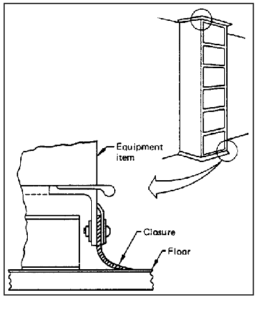
11.4.4 Example Closures and Covers Design Solutions
{A}
Special hardware items, such as metal or rubber trim strips, moldings,
fairings, or cover plates, can be used to seal off the inaccessible
areas and meet the closure requirements. An example is shown in
Figure 11.4.4-1.
Reference: 1, Figure B-23,
p. B-13; NASA-STD-3000 99
11.5
MOUNTING HARDWARE
{A}
11.5.1 Introduction
{A}
This section includes design considerations and requirements for installation
and mounting of hardware and equipment. This section covers items such
as access, visibility, spacing between components, alignment aids, shims,
and washers.
11.5.2 Mounting Hardware Design Considerations
{A}
For manned space modules that will require in-flight checkout, maintenance,
and replacement of hardware, it is very important that the hardware
components be mounted in such a way that the crew can perform these
operations with minimal inconvenience. This requires attention to hardware
design details such as accessibility, clearance between components,
forces to disengage the items, alignment, and shimming.
11.5.3 Mounting Hardware
Design Requirements
{A}
11.5.3.1 General
Mounting Design Requirements
{A}
The following general requirements apply to mounting hardware:
a. Equipment Mounting - Equipment items shall be designed so that they
cannot be mounted improperly.
b. Drawers and Hinged Panels - Subsystem components which are frequently
pulled out of their installed position for checkout shall be mounted
on equipment drawers or on hinged panels.
(Refer to Paragraph 11.3.3, Drawer and Rack
Design Requirements, for specific requirements.)
c. Layout - Components shall be mounted so that a minimum amount of
place-to-place hand movements will be required during operations.
d. Covers or Panels - Removal of any replaceable item shall require
opening or removing a minimum number of covers or panels.
(Refer to Paragraph 11.4.3, Closures and Covers
Design Requirements, for specific requirements.)
e. Installation/Removal Force - Hardware mounted into a capture-type
receptacle that requires a push-pull action shall require a force less
than 156N (35 lbf) to install or remove.
(Refer to Paragraph 4.9.3, Strength
Design Requirements.)
f. Rear Access - Equipment to which rear access is required shall be
free to open or rotate to their full distance travel and remain in the
open position without being supported by hand.
g. Tools - Whenever possible, items shall be replaceable with a common
hand tool.
(Refer to Paragraph 11.2.3, Tool Design Requirements,
for specific tool requirements.)
h. Direction of Removal - Replaceable items shall be removable along
a straight or slightly curved line, rather than through an angle.
i. Visibility - Visual access for alignment and attachment of equipment
shall be provided.
(Refer to Paragraph 11.5.3.2, Alignment Devices
Design Requirements, for specific alignment requirements.)
j. Spacing - Mounting bolts and fasteners shall be spaced far enough
from other surfaces to allow personnel to manipulate them.
(Refer to Paragraph 11.2.3.6, Tool Access
Design Requirements, and Paragraph 11.9.3, Fastener
Design Requirements, for specific requirements.)
k. Number of Mounting Bolts - Use the minimum number of fasteners,
consistent with stress and vibration requirements, so that the crewmember's
workload is minimized.
(Refer to Paragraph 11.9.3.1, General Fastener
Design Requirements, for other fastener requirements.)
l. Shims, Washers - Where shims or washers are permitted in an IVA
application, the following rules shall be followed:
1. Shims shall be bound together in a shim assembly.
2. Shim assemblies shall be tethered or restrained at the location
or point of use and identified as to location or point of use.
3. A similar requirement shall be observed for washers and other loose
items which are auxiliary connector/fastener devices.
11.5.3.2 Alignment
Devices Design Requirements
{A}
The following alignment methods for replaceable hardware shall be used:
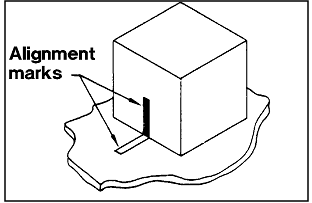
a. Alignment Marks - If proper interface orientation is not obvious
by virtue of external geometry or if adequate visibility cannot be provided
for hardware that will be mounted on-orbit, the hardware design shall
incorporate alignment marks and/or orientation arrows.
1. Alignment marks shall be applied to both mating parts and the marks
shall align when the parts are in the operational position.
2. An alignment mark shall consist of a straight line of a width and
length appropriate to the size of the item.
Alignment marks shall be clearly visible to a crewmember performing
hardware removal/replacement.
(Also see Paragraph 9.5.3.1.5,
Alignment Marks/ Interface Identification Design Requirements.)
b. Alignment Devices - Guide pins or their equivalent shall be provided
to assist in alignment of hardware during mounting, particularly on
modules that have integrated connectors.
(Refer to Paragraphs 11.10.3.3, Structural
Connectors Design Requirements, and 11.10.3.4,
Optical Connectors Design Requirements, for connector alignment requirements.)
c. Keying - All replaceable hardware shall be designed so that it will
be physically impossible to install it in the wrong orientation or location.
d. Replaceable Hardware Identification - Replaceable hardware shall
be identified with nomenclature that aids the crewmember in identifying
the hardware name, alignment of the hardware, and the correct use of
attaching parts.
(Refer to Paragraph 9.5.3, Labeling
and Coding Design Requirements, for specific requirements.)
11.5.4 Example Mounting Hardware Design Solutions
{A}
Examples of successful mounting hardware designs from previous space
missions are included in this section.
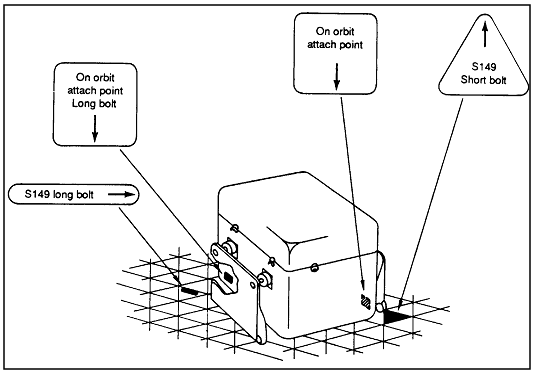
a. Alignment Marks - Figure 11.5.4-1
shows an example of how to use alignment marks. The alignment mark size
on the equipment and the mating structure shall align when the parts
are in the operational position.
b. Identification of Movable Equipment - Moving equipment from the
launch location to the orbital or planetary operational location will
require providing information to the crewmember which shows the correct
use of the attaching parts. Figure 11.5.4-2
shows an example of attachment interface markings on movable equipment.
11.6
HANDLES AND GRASP AREAS (FOR PORtable ITEMS)
{A}
11.6.1 Introduction
{A}
This section includes design criteria for handles and grasp areas.
The requirements for these items are similar in that they both pertain
to use with removable or portable units. However, these requirements
should not be confused with handholds and handrails.
(Most of the design criteria for handholds and handrails is provided
in Paragraph 11.8, Mobility Aids.
Paragraph 11.8 also contains criteria
on equipment mobility aids other than handles and grasp areas.)
Figure
11.5.4-1 Example of Mounting Hardware Alignment Marks
Reference: 1, para 4.8.4.1,
p. 4.8-6; NASA-STD-3000 17
Figure
11.5.4-2 Example of Attachment Interface Markings on Movable Equipment
Reference: 1, Figure B-28,
p. B-15; NASA-STD-3000 16
(Refer to Paragraph 11.3.3, Drawer and Rack
Design Requirements, for requirements pertaining to handles and mechanisms
for drawers and racks.)
11.6.2 Handle and Grasp Area Design Considerations
{A}
Handle or grasp area designs should consider the following factors:
a. The mass properties of the item to be moved.
b. The operational location of the item relative to other items.
c. The manner in which the item is to be handled.
d. The distance the item needs to be moved.
e. The frequency with which the item may need to be handled.
f. The additional uses which the handle may serve, such as the anchor
for a tether or as a handhold.
g. Handles should be located on either side of the center of mass.
h. The number and location of handles shall be determined by the mass,
size, and shape of the object. (Refer to
Paragraph 8.8.2).
i. Handles should be recessed or fold flush with surfaces to minimize
potential for snagging clothing, equipment, or restraints.
11.6.3 Handle and Grasp
Area Design Requirements
{A}
11.6.3.1 General
Handle and Grasp Area Design Requirements
{A}
The following general requirements shall be observed:
a. Provide Handles - All removable or portable units shall be provided
with handles or other suitable means for grasping, tethering, handling,
and carrying.
b. Exempt Items - Items less than 0.03 m3 (1 ft3)
whose form factor (shape) permits them to be handled easily shall be
exempt from the above requirement.
c. Labeling of Nonhandling Areas - Built-in features that appear to
be suitable for grasping/tethering/ restraining and are not suitable
must be labeled to indicate that these features are not suitable for
these purposes.
(Refer to Paragraph 9.5.3, Labeling
and Coding Design Requirements, for specific requirements.)
11.6.3.2 Handle
and Grasp Area Location Design Requirements
{A}
The following general location requirements of handles or grasp areas
shall apply:
a. Interference - Handles and grasp areas shall be located so that
they do not interfere with equipment location or maintenance.
b. Clearance - Clearances shall be provided between handles and obstructions
consistent with anthropometric requirements.
c. Tether Attachments - Handles and grasp areas shall be suitable as
tether or bracket attachment positions.
d. Location - The location of handles or grasp areas shall be such
that they do not constitute passageway hindrances or safety hazards.
If they must be located in passageways they shall be recessed and designed
to minimize chance of crewmember injury or inadvertent contact.
e. Location/Front Access - Handles and grasp areas shall be placed
on the accessible surface of an item consistent with the removal direction.
11.6.3.3 Nonfixed Handles Design Requirements
{A}
Hinged, foldout, or attachable (i.e., nonfixed) handles shall comply
with the following:
a. Locked or Use Position - Nonfixed handles shall have a stop position
for holding the handle perpendicular to the surface on which it is mounted.
b. One-Handed Operation - Nonfixed handles shall be capable of being
placed in the use position by one hand and shall be capable of being
removed or stowed with one hand.
c. Tactile or Visual Indicators - Attachable/removable handles shall
incorporate tactile and/or visual indication of locked/unlocked status.
11.6.3.4 Handle Dimensions Design Requirements
{A}
IVA handles for movable or portable units shall be designed in accordance
with the minimum applicable dimensions in
Figure 11.6.3.4-1.
Figure
11.6.3.4-1 Minimum IVA Handle Dimensions for IVA Applications
| Illustration |
Type of Handle |
Dimensions in mm (in inches) |
| (Bare Hand) |
| X |
Y |
Z |
.gif) |
Two-finger bar |
32 (1-1/4) |
65 (2-1/2) |
75 (3) |
| One-hand bar |
48 (1-7/8) |
111 (4-3/8) |
75 (3) |
| Two-hand bar |
48 (1-7/8) |
215 (8-1/2) |
75 (3) |
.gif) |
T-bar |
38 (1-1/2) |
100 (4) |
75 (3) |
.gif) |
J-bar |
50 (2) |
100 (4) |
75 (3) |
.gif) |
Two-finger recess |
32 (1-1/4) |
65 (2-1/2) |
75 (3) |
| One-hand recess |
50 (2) |
110 (4-1/4) |
90 (3-1/2) |
.gif) |
Finger-tip recess |
19 (3/4) |
- |
13 (1/2) |
| One-finger recess |
32 (1-1/4) |
- |
50 (2) |
Curvature of handle or edge
(DOES NOT PRECLUDE USE OF OVAL HANDLES) |
Weight of item:
|
Minimum diameter
|
|
Up to 6.8 kg
(up to 15 lbs) |
D = 6 mm (1/4 in) |
Gripping efficiency is best if finger can curl around
handle or edge to any angle of 2/3 π rad (120°) or more
|
6.8 to 9.0 kg
(15 to 20 lbs) |
D = 13 mm (1/2 in) |
9.0 to 18 kg
(20 to 40 lbs) |
D = 19 mm (3/4 in) |
Over 18 kg
(Over 40 lbs) |
D = 25 mm (1 in) |
| T-bar post |
T = 13 mm (1/2 in) |
Reference: 2, Figure 48,
p. 197; NASA-STD-3000 18
11.7
RESTRAINTS
{A}
11.7.1 Introduction
{A}
This section provides the design considerations, requirements, and
example design solutions for personnel and equipment restraints. Portable
and fixed foot restraints, body restraints, and equipment restraint
devices are included.
The related topic of portable and fixed handholds and handrails are
found in Paragraph 11.8, Mobility
Aids. Placement of restraints within the space module is described in
Paragraph 8.9, Mobility
Aids and Restraints Architectural Integration. The integration of restraints
with workstations is addressed in
Paragraph 9.2.4.2.3, Work Station Restraints and Mobility Aid Design
Requirements.
{A}
11.7.2.1 Introduction
{A}
This section provides the personnel restraints design considerations,
requirements, and examples. Foot restraints, body restraints, and sleep
restraints are described.
11.7.2.2 Personnel
Restraints Design Considerations
{A}
Personnel restraints are required at liftoff, during major thrusting
maneuvers, microgravity/partial-gravity operations, and during return-to-earth
operations. This section includes seat belts, shoulder harnesses, fixed
and portable foot restraints, and body restraints. Donning/ doffing,
loads, materials, color, temperature limits, and dimensional requirements
are included for each type of personnel restraint.
(Refer to Paragraph
14.4, EVA Workstations and Restraints, for EVA restraint design
considerations and requirements.)
(Refer to Paragraph 11.8, Mobility
Aids, for the related topic of handholds and handrails.)
(Refer to Paragraph 9.2.4, Human/Workstation
Configuration, for design considerations and requirements related to
integration of restraints and workstations.)
Openings, holes, ductwork, and protrusions in and around equipment
have been used by crewmembers as informal microgravity body restraints.
Equipment designers must take this into account when designing equipment.
These informal restraints are acceptable for short-duration tasks. They
should not be the only method of restraint for long-duration operations
where IVA foot restraints or fixed body restraints should be considered.
Foot restraints (and/or body restraints) may be required for tasks
requiring precision. Unique foot restraint designs should be minimized
and standardized design should be maximized. Any portion of the restraint
worn on the foot shall be as low in mass as possible. In order to aid
foot restraint ingress and egress, handholds that are located between
the waist and shoulder should be available at all workstations. Commonalty
requirements for foot restraint attachment, finish, durability, and
color should be incorporated into the design.
Foot restraints can be built into the equipment or into the crewmember's
shoes.
(Refer to Paragraphs 9.2.4.2.3,
Workstation Restraints and Mobility Aids Design Requirements, and 8.9.3.2,
IVA Restraint Locations Design Requirements, for foot restraint location
requirements.)
11.7.2.3 Personnel
Restraints Design Requirements
{A}
11.7.2.3.1
General Personnel Restraints Design Requirements
{A}
All EVA and IVA personnel restraints (i.e., seat belts, shoulder harnesses,
body restraints, foot restraints, and sleep restraints) shall comply
with the following requirements:
(Refer to Paragraph 14.4.3.4,
EVA Crew Restraint Design Requirements, for EVA-unique requirements.)
a. Comfort - Restraint forces shall be reasonably distributed over
the body to prevent discomfort and shall not require conscious effort
to remain constrained.
b. Allowable Comfort Time - Comfort of the IVA restraint system shall
allow for a four-hour uninterrupted use.
c. Muscular Tension - Restraint design shall minimize or eliminate
muscular tension.
d. Anthropometric Range - All personnel restraints shall accommodate
the specific population of users for whom the system is to be designed.
e. Microgravity Posture - Personnel restraints to be used in microgravity
applications shall be designed for microgravity posture compatibility.
(Refer to Paragraph 3.3.4.3, Neutral
Body Posture Data - Design Requirements, for specific anthropometric
requirements.)
f. Cleaning and Repair - The personnel restraint system shall be capable
of being cleaned and repaired on-orbit.
11.7.2.3.2 Foot
Restraint Design Requirements
{A}
11.7.2.3.2.1 General Foot Restraint Design Requirements
{A}
The following general requirements apply to all fixed and portable
foot restraints:
(Refer to Paragraph 14.4.3.4,
EVA Crew Restraint Design Requirements, for EVA-unique foot restraint
requirements.)
a. Range of Motion - All foot restraints shall maintain foot position
to allow the crewmember a complete range of motion (roll, pitch, and
yaw).
(Refer to Paragraph 3.3.3.2.2,
Body Posture Design Considerations, for further information.)
b. Comfort - Foot restraints shall provide comfortable support.
c. Interchangeability - Attachment interfaces for foot restraints (portable-to-portable
and fixed-to-fixed) shall be interchangeable throughout the space module.
d. Positive Retention - The foot restraint shall be positive and firmly
hold the user in the desired position.
e. Load Reaction - Foot restraints shall provide the capability to
react to loads applied by the crewmember.
f. Abrasion Resistance - Reinforcements shall be provided for any fabric
areas exposed to high abrasion.
g. Ventilation - IVA foot restraints and covers shall allow ventilation
to the feet.
h. Fixed Foot Restraints - The fixed foot restraint shall be capable
of being removed for replacement/repair.
i. Portable Foot Restraints - The portable foot restraint shall be
capable of being installed and removed easily and quickly without tools.
11.7.2.3.2.1 Foot Restraint Donning/Doffing Design Requirements
{A}
Foot restraints shall comply with the following donning and doffing
requirements:
(Refer to Paragraph 14.4.3.4,
EVA Crew Restraint Design Requirements, for EVA-unique foot restraint
donning and doffing requirements.)
a. Donning - Foot restraints shall be attached or donned with minimum
effort.
b. Quick Release - Rapid ingress/egress shall be inherent to all IVA
foot restraints.
c. No-Hand Operation - The use of hands for placing/ removing the foot
shall not be required for foot restraint ingress/egress.
d. Handholds - Handholds or structure between waist and shoulder shall
be available at all foot restraint locations to aid foot restraint ingress
and egress.
(Refer to Paragraph 8.9.3.1, Required
IVA Mobility Aid Integration Design Requirements, for the specific requirements.)
e. Entrapment - All foot restraints shall minimize danger of entrapment.
A positive means of releasing the foot from the restraint shall be provided.
11.7.2.3.2.2 Foot Restraint Loads Design Requirements
{O}
IVA foot restraints must meet the following load requirements:
(Refer to Paragraph 14.4.3.4,
EVA Crew Restraint Design Requirements, for EVA restraint loads.)
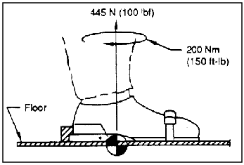
a. Tension Loads - Foot restraints shall be designed to withstand a
tension load of 445 N (100 lbf) as a minimum (see
Figure 11.7.2.3.2.3-1.)
Reference: 1, Figure 4.2-3;
NASA-STD-3000 19
b. Torsion Loads - The restraints shall withstand a torsion load of
200 Nm (150 ft-lb) as a minimum with the torsion vector normal to the
floor. (See Figure 11.7.2.3.2.3-1.)
c. Factor of Safety - The yield factor of safety shall be 1.10 and
ultimate factor of safety shall be 2.00.
11.7.2.3.2.3 Foot Restraint Durability and Color Design Requirements
{A}
The durability and color of IVA and EVA foot restraints shall comply
with the following:
a. Durability - Finish shall be durable, smooth, and scratch resistant
to prevent undue wear on footwear.
b. Color - Color for all foot restraints of a given type shall have
a contrast ratio of approximately 10:1 or greater with the background.
11.7.2.3.3 Body Restraint Design Requirements
{A}
11.7.2.3.3.1 Body Restraint Donning/Doffing Design Requirements
{A}
The following crewmember body restraint donning and doffing requirements
shall apply to all tether attachments, seat belts, and shoulder harnesses:
a. Latching Mechanisms - The latching mechanism attachment will require
a positive action by the crewmember to both latch and unlatch the mechanism.
b. One-Handed Operation - The latching mechanism shall have the capability
of being latched and unlatched with one hand.
11.7.2.3.3.2
Body Restraint Loads Design Requirements
{O}
The following load requirements shall apply to seat belts, shoulder
harnesses, and IVA tethers:
(Refer to Paragraph 14.4.3.4,
EVA Crew Restraint Design Requirements, for EVA-unique body restraint
load requirements.)
a. Seat Belts and Shoulder Harnesses - IVA seat belts and shoulder
harnesses installed at stations designated as occupied during launch
and landing shall be designed so the occupant making proper use of the
equipment will not suffer serious injury when the following ultimate
inertia forces acting separately are imposed on the crewmember:
1. Downward (Eyeballs Up): 2.0 -Gz
2. Backward (Eyeballs Out): 9.0 -Gx
3. Sideward : 1.5 ± Gy
4. Upward (Eyeballs Down): 4.5 +Gz , or any lesser force that will
not be exceeded when the landing loads resulting from impact with an
ultimate descent velocity of five ft/sec at design landing weight.
(Refer to Paragraph 5.3.3.1, Linear
Acceleration Design Requirements for acceleration coordinate system
and requirements.)
b. Body Harnesses - Body harnesses shall have lifting attach points
(D-rings) which can be used in lifting or hoisting the crewmember during
egress operations in a 1-g environment. The body harness shall be designed
to support the load of the crewmember while being lifted or hoisted.
The body harness can be designed to be an integral part of the seat
belt and shoulder harness restraint system or be designed as a separate
harness to be worn in addition to the seat belt and shoulder harness
restraint system.
c. Tether Attachments - IVA tether attachments shall be capable of
sustaining a load of 756 N (170 lbs) along the longitudinal axis. They
shall be designed so as to preclude any side loading.
d. Attach Points for Tether Attachment - IVA translation and mobility
handhold tether attachment attach points shall be designed to a minimum
ultimate load of 902 N (250 lbf) in any direction.
11.7.2.3.3.3 Body Restraint Finish and Color Design Requirements
{A}
Markings, labeling, and colors shall be in accordance with
Paragraph 9.5.
11.7.2.3.3.4 Body Restraint Dimensional Design Requirements
{A}
The following dimensional requirements shall apply to all seat belts,
shoulder harnesses, and tethers:
(Refer to Paragraph 14.4.3.4,
EVA Crew Restraint Design Requirements, for EVA-unique restraint dimensional
requirements.)
a. Commonalty - Seat belts, shoulder restraints, waist restraints,
and tether attachments shall be uniform in size, shape, and method of
operation within the limits of task performance and other design tradeoffs.
b. Size - Task requirements for which the attachment is designed shall
dictate the actual size of the hooking and latch mechanism.
11.7.2.3.4 Sleep Restraints Design Requirements
{OP}
Sleep restraint design shall meet the following requirements:
a. Extremity Restraint - Sleep restraints shall include provisions
to prevent leg and arm float and prevent the head from moving during
sleep.
b. Trapped Air - Sleep restraint design shall eliminate excessive or
unevenly distributed trapped air.
c. Individual Sleep Restraints - One sleep restraint shall be provided
for each crewmember.
d. Stowage, Transport, Cleanability - Sleep restraints shall be easily
stowable, transportable, and cleanable on-orbit.
e. Features - A sleep restraint shall incorporate the following features:
1. Adjustable, flexible restraint straps.
2. Arm slits.
3. Adjustable, removable pillows/head- strap.
4. Adjustable thermal protection.
f. Opening/Closing - A sleeping bag opening/closing device that extends
the full length of the bag shall be provided.
g. Torso Restraint - Torso restraining straps shall be provided to
allow the crewmembers to restrain themselves in their choice of sleeping
position.
h. Opening/Closing - The opening/closing device shall be capable of
easy use, including quick opening in case of emergency.
i. Opening/Closing Device Replacement - The opening/ closing device
shall be easily replaceable.
11.7.2.4 Example Personnel Restraint Design Solutions
{O}
The following figures provide examples of personnel restraint design
solutions:
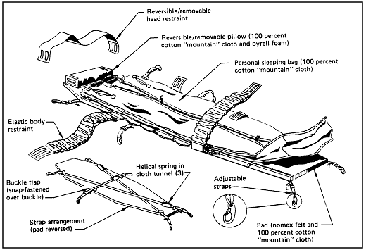
Figure 11.7.2.4-1 shows the sleep
restraint configuration used on the orbiter.
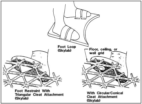
Figure 11.7.2.4-2 shows examples of
foot restraints used in the Skylab.
Figure 11.7.2.4-3 show an example
of a lower leg restraint available on the Skylab.
Figure 11.7.2.4-4 lists the types
of body restraints versus crew tasks that were used on the Skylab.
Reference: 150, p. 3.18-26;
NASA-STD-3000 20
Reference: 155, Page
3-47 - 3-49; NASA-STD-3000 101
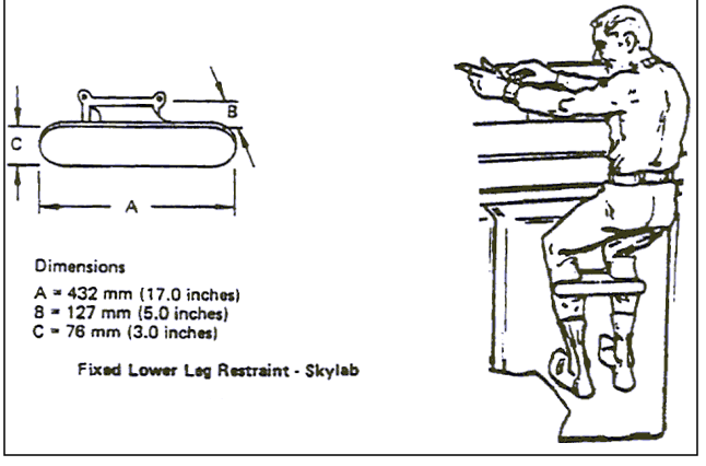
Note: Dimensions of lower leg restraint: A (length) = 432 mm
(17.0 in), B (distance from mounting structure) = 127 mm (5.0
in), C (height), 76 mm (3 in). |
Reference: 155, pp. 3-51,
3-53; NASA-STD-3000 102
Figure
11.7.2.4-4 Skylab Crew Tasks Vs. Body Restraints
Skylab Crew Tasks Vs. Body Restraints
| Crew task |
Body restraint mode |
| Hand-hold |
Toe (foot loop) |
Foot (triangular cleat) |
| Meal preparation |
x |
|
x |
| Eating |
x |
|
x |
| Flight data management |
x |
|
x |
| Consoles/vehicle operations |
x |
|
x |
| Body waste collection |
x |
x |
|
| Activation/deactivation |
x |
|
x |
| Experiment operations |
x |
|
x |
| General crew task, maintenance, and housekeeping |
x |
|
x |
| Whole-body cleaning |
x |
x |
|
| Stowage operations |
x |
|
x |
| Equipment transfer |
x |
|
x |
| Personal hygiene |
x |
x |
x |
Reference: 155, Page
3-54; NASA-STD-3000 103
Skylab flight experience demonstrated that foot restraints are adequate
for most tasks. A pelvic restraint, for use with portable foot restraints
at the Apollo Telescope Mount Control Station, was not required. The
adjustable grid restraint provided adequate force cancellation, stability,
and reach capability.
For most simple, short-term tasks a handhold or any graspable structure
provides sufficient restraint.
11.7.3 Equipment Restraints
{A}
Video clips associated with this section are:
{A}
This section provides the design considerations, requirements, and
examples of equipment restraints required to retain tools and equipment
at workstations. These equipment restraints include tethers, tape, bungee
cords, Velcro, and other such devices.
(Refer to Paragraph 11.9, Fasteners,
and Paragraph 11.8.3, Equipment Mobility Aids,
for related equipment restraint design considerations and requirements.)
(Refer to Paragraph 8.9,
Mobility Aids and Restraints Architectural Integration, for equipment
restraint location design considerations and requirements.)
(Also refer to Paragraph 13.4.3.2,
Hardcopy Information Management Design Requirements, for specific requirements
for restraining documents and loose papers.)
11.7.3.2 Equipment
Restraint Design Considerations
{A}
Temporarily restraining equipment in microgravity is very important.
Everything from large equipment modules to small nuts and bolts needs
to be secured at the storage and work sites to keep them from floating
away. A variety of means have been employed in previous space modules
(e.g., gray tape, bungee cords, Velcro, tethers, and bags) with varying
degrees of success.
The restraints need to be standardized, multipurpose, easy to use,
require no tools to operate, and easily stowable.
Adhesive-type restraints (tapes) need to be easy to peel off of the
roll, easy to tear, and should not leave an adhesive residue when removed
from a surface.
11.7.3.3 Equipment
Restraint Design Requirements
{A}
All IVA and EVA equipment restraints shall be designed to the following
requirements:
a. Hand Operated :
1. Equipment restraints shall be designed such that tools are not required
to attach or detach the restraint.
2. Equipment restraints shall be designed such that they can be attached/detached
by either the left or right hand.
b. Blind Operation - The equipment restraints shall be designed such
that they can be attached/detached without having to look at them.
c. Adjustability - Provide the capability to adjust the restraint to
adapt to a wide range of sizes of the items to be restrained and to
provide the user with the capability to restrain the item at a preferred
location relative to the restraint attachment points. This does not
preclude fixed- length tethers used for specific applications.
d. Positive Restraint - The restraint shall secure the item in such
a way that the item will not come loose due to inadvertent touching,
air currents, vehicle dynamic motions, or due to other predictable environmental
conditions.
e. Cause No Damage - The equipment restraint shall be designed such
that it cannot pinch, abrade, or cut the item to be restrained or the
interfacing surfaces and adjacent hardware.
f. No Adhesive Residue - Adhesive equipment restraints shall not leave
an adhesive residue on the item or on the spacecraft surface when the
adhesive restraint is detached.
g. Tethers:
1. Common attachment method - All equipment tethers shall use a common
attachment method.
2. Tether attachment points - All equipment items that require tethering
shall have a standardized tether hook receptacle as an integral part
of the item. This standardized receptacle shall also be provided on
the interfacing surface to which the item is to be secured.
3. Tether lock status indication - The tether hook shall be designed
in such a way that it will be easy to recognize when the hook is locked/unlocked
in both day and night lighting conditions.
h. Loads :
1. Minimum load - The minimum design load shall be based on the expected
crew-imposed and environmental loads to be applied to the item in the
normal operating conditions.
2. Maximum load - The maximum design load shall be based on the resultant
load imposed by a crewmember attempting to dislodge a restrained item
that has become entrapped in adjacent hardware. The stress of this activity
should not exceed the design load of the surface to which the restraint
is attached or the design load of the entrapping hardware (i.e., the
restraint should break before the item, attachment surface, of entrapping
hardware breaks).
(Refer to Paragraph 4.9.3, Strength
Design Requirements, for definition of maximum crew imposed loads.)
i. Color - Equipment restraints shall be of a standardized color to
distinguish them from other types of loose equipment or items that will
be restrained.
(Refer to Paragraph 9.5.3.2, Coding
Design Requirements, for color selection criteria.)
j. Grounding :
(Refer to Paragraph 6.4.3, Electrical
Hazards Design Requirements, for specific requirements.)
k. Commonalty - Provide Commonalty of design for equipment restraints
to the maximum extent possible.
l. Individual Restraints :
1. Individual restraints shall be designed to restrain one hardware
item only.
2. Individual restraints shall be used when the restrained item is
large in size, sensitive, or delicate or when attachments are difficult
or complex in operation
m. Group Restraints :
1. Group restraints shall be used to restrain like-sized items wherever
possible.
2. Group restraints shall provide a system that allows the removal
of one item at a time.
n. Throw-Away Restraints - Any restraint device that is utilized during
vehicle launch, and upon activation or usage removal is discarded, shall
meet the following requirements:
1. Large throw-away restraints shall be designed to be torn apart or
be of soft, crushable materials to accommodate the openings of onboard
trash collection/disposal systems.
2. The throw-away restraints shall be color coded as a throw-away item.
(Refer to Paragraph 9.5.3.2, Coding
Design Requirements, for specific requirements.)
o. Velcro - When Velcro is used as a restraint, the item to be restrained
will be equipped with hook-type Velcro and the restraining surface will
be equipped with pile-type Velcro.
11.7.3.4 Example Equipment Restraint Design Solutions
{O}
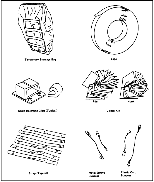
Figure 11.7.3.4-1 shows examples of
previously used equipment restraints.
a. Temporary Stowage Bags - These bags provided an acceptable method
of temporary retention of equipment during Skylab missions. These bags
should be designed so that the contents are visible (i.e., use transparent
plastic or netting).
b. Gray Tape - Apollo, Skylab, and shuttle missions have used gray
tape extensively as a temporary restraint for IVA operations. Use in
EVA was not always acceptable because the adhesive capabilities may
have been affected by temperature extremes.
c. Cable Restraint Clips - These were used extensively in Apollo and
Skylab missions.
d. Velcro - Velcro provides an acceptable equipment restraint.
NOTE: The adhesive holding the Velcro pad must be stronger than the
hook/pile retention capability. Adhering qualities of the hook and pile
are quite material dependent. Temperature constraints may prohibit EVA
use.
e. Straps With Snaps and/or Velcro
NOTE: Crewmembers require handholds or foot restraints to mate female
snaps to spacecraft structure studs in microgravity environment. Snaps
are also difficult to align during EVA.
f. Metal and Elastic Bungee Springs with Snaps or Flat Hooks - These
are recommended for IVA use only. These were the most widely accepted
retention devices used on Apollo, Skylab, and shuttle missions.
NOTE: Both the metal springs and the elastic tend to stretch after
extended use and snaps are difficult to attach to structure-mounted
interfacing studs in a microgravity environment.
g. EVA Tethers - Fixed length, adjustable, and retractable tethers
have been used extensively in EVA operations but can also be used for
IVA operations.
h. Rubber Bands - Experience on Skylab missions has shown that rubber
bands proved to be an excellent device to hold flight manuals and checklists
from inadvertently opening in microgravity.
i. Other Devices - There are many other equipment restraint devices
that have been tried. These include pip pins, dogleash clips, pinch
clamps, and snap rings.
(Refer to Reference 155,
Section 3.2.2, for examples of equipment restraints used on the Skylab.)
Reference: 150, p. 3.4-2;
NASA-STD-3000 21
11.8
MOBILITY AIDS
{A}
11.8.1 Introduction
{A}
This section contains design considerations, requirements, and examples
for personnel and equipment mobility aids. Design criteria include dimensions,
coding, texture, design loads, temperature limits, and mounting.
(Also, refer to Paragraph
8.9, Mobility Aids and Restraints Architectural Integration.)
Items such as tethers, hooks, restraints, and temporary stowage devices
which interface with mobility aids are described in
Paragraph 11.7. Handles and grasp areas on the portable equipment
covered are detailed in Paragraph 11.6.
11.8.2 Personnel Mobility
Aids
{A}
11.8.2.1 Handhold
and Handrail Design Considerations
{A}
Handholds and handrails are the hardware interfaces used for crewmember
mobility aids. They are necessary in both IVA and EVA applications for
crewmembers to use as they move from place to place during the performance
of their tasks.
Handholds or handrails may also provide local protection to the vehicle/payload
components. They also serve as convenient locations for temporary mounting,
affixing, or restraint of loose equipment and as attachment points for
equipment and personnel safety tethers. Handholds provide adequate restraint
for low force, short- time manual tasks such as inspection, monitoring,
and control/switch actuation.
Handholds and handrails can be permanently installed or portable.
Handhold areas are typically located around the edges of hatches, bulkheads,
equipment, containers, and stowage lockers.
(Refer to Paragraph 8.9,
Mobility Aids and Restraints Architectural Integration, for details.)
Handholds and handrails are primarily fabricated from metals. Other
rigid, semi-rigid, or cloth materials may be used in accordance with
Reference 24.
(Refer to Paragraph 14.5.2.2,
EVA Mobility Aids Design Considerations, for EVA-unique considerations.)
11.8.2.2 Handhold
and Handrail Design Requirements
{A}
This section provides the design requirements for handholds and handrails.
These requirements shall apply to both IVA and EVA applications except
where EVA-unique requirements are specifically identified.
11.8.2.2.1 Handhold
and Handrail Dimensions Design Requirements
{A}
All handholds and handrails shall adhere to the following cross-section
design requirements:
a. Standardization - Cross-sectional dimensions of handholds and handrails
shall be standardized throughout the space module to provide a uniform
interface for mounting items such as brackets and tether hooks.
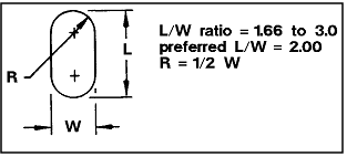
b. Cross-Section Shape - Handholds and handrails cross-section shape
shall be designed such that the crewmember's hand or attached brackets
will be stabilized (i.e., circular cross-section shall not be used).
Refer to Figure 11.8.2.2.1-1, IVA
Handhold Cross Section.
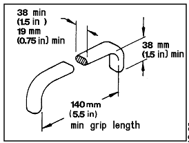
c. IVA Handhold Minimum Dimensions - All IVA handholds shall have a
minimum of 14 cm (5.5 in.) grip length and a minimum of 3.8 cm (1.5
in.) clearance between the lower surface of the handgrip and the surface
on which it is mounted. (Refer to Figure
11.8.2.2.1-2.)
(Refer to Paragraph 11.8.2.2.3, Handhold
and Handrail Texture Design Requirements, for other shape requirements.)
(Refer to Paragraph 14.5.3.2,
EVA Mobility Aids Design Requirements, for EVA-unique handhold/handrail
dimensions.)
Text: L/W ratio = 1.66 to 30. Preferred L/W = 2.00. R = 1/2 W |
Reference: 1, Figure 4.1-4,
p. 4.1-2 With Updates; NASA-STD-3000 22
Reference: 1, Figure 4.1-4,
p. 4.1-2 With Updates; NASA-STD-3000 23
11.8.2.2.2 Handhold
and Handrail Coding Design Requirements
{A}
Handholds and handrail coding shall be such that the crew may locate
them with ease:
a. Standard Color - The color of all handholds/ handrails shall be
standardized within the space vehicle.
b. Contrast Ratio - The color valve shall have a contrast ratio of
5:1 or greater with the background where distinctive identification
is required.
(Refer to Paragraph 9.5.3, Labeling
and Coding Design Requirements, for other general and specific color
coding requirements.)
11.8.2.2.3
Handhold and Handrail Finish Design Requirements
{A}
Handhold and handrail texture shall be such that the crew may locate
them by feel and grasp them with ease:
a. Identical Finish - The finish of all handholds/ handrails shall
be identical to enhance identification.
b. Non-Slip Surface - Handholds and handrails shall have a non-slip
surface with no burrs, sharp edges, or protrusions.
(Refer to Paragraph 6.3.3, Mechanical
Hazards Design Requirements, for other applicable requirements.)
c. Durability - The finish of all handholds and handrails shall be
resistant to scratches, wear, flaking, and pealing.
11.8.2.2.4 Handhold
and Handrail Design Loads Design Requirements
{O}
All fixed and portable IVA handholds and handrails shall be designed
to a minimum ultimate load of 1113 N (250 lbs) applied in any direction
without failure or damage that precludes full utilization by crewmembers.
(Refer to Paragraph 14.5.3.2,
EVA Mobility Aid Design Requirements, for EVA-unique handhold/handrail
design load requirements.)
11.8.2.2.5
Handhold and Handrail Temperature Design Requirements
{A}
Surface temperature design requirements for handholds and handrails
differ with the particular use (IVA or EVA). IVA handhold/handrail shall
adhere to the requirements in Paragraph
6.5.3, Touch Temperature Design Requirements. EVA handhold/handrail
shall adhere to the requirements in
Paragraph 14.2.3.11 EVA Touch Temperature and Pressure Design Requirements
and Paragraph 14.5.3.2 h, EVA
Mobility Aids Design Requirements.
(Refer to Paragraph 6.5.3, Surface
Touch Temperature Design Requirements, for IVA handhold and handrail
surface temperature design requirements.)
(Refer to Paragraph 14.5.3.2,
EVA Mobility Aid Design Requirements, for EVA-unique handhold and handrail
surface temperature design requirements.)
11.8.2.2.6 Handhold
and Handrail Mounting Design Requirements
{A}
The following requirements shall apply to all handhold and handrail
mounting:
a. Stability - All fixed and portable handholds and handrails shall
be designed so that when installed there is no instability (i.e., looseness,
vibration, or slippage).
b. Portable Handhold and Handrail Lock Status Indication - Portable
handhold and handrails shall provide a positive indication of when they
are in the locked position.
c. Visibility and Accessibility - Handholds and handrails shall be
mounted so that they are clearly visible and accessible.
(Refer to Paragraph 8.9.3.1, IVA
Mobility Aid Locations - Design Requirements, for specific requirements.)
(Refer to Paragraph 11.8.2.2.2, Handhold
and Handrail Coding Design Requirements, for color coding requirements.)
d. Handhold Removal - Fixed handholds shall be removable with common
tools.
e. Safety - Handrails and associated mounting provisions shall be designed
so as to preclude snagging of body, clothing, and/or loose equipment
(e.g., cables).
11.8.3 Equipment Mobility
Aids
{A}
11.8.3.1 Equipment
Mobility Aid Design Considerations
{A}
The mobility aid design considerations for equipment are as follows:
(Refer to Paragraph 14.5.2.6,
EVA Equipment Transfer Design Considerations, for EVA-unique considerations.)
a. Tethers may be used on equipment items being transferred but are
not generally required for IVA.
b. Mechanical transfer aids (e.g., taut line, extendable boom) should
be provided for use in guiding large (size and/or mass) equipment items
during transfer.
c. Equipment transfer of two crewmembers should be considered where
transfer of large equipment may cause injury to the crewmember or damage
to the space module.
d. Removable equipment mobility aids should be provided where needed
to provide clearance and access passage.
11.8.3.2 Equipment
Mobility Aid Design Requirements
{A}
The following equipment mobility and requirements are applicable to
both IVA and EVA:
(Refer to Paragraph 11.6.3, Handle and Grasp
Area Design Requirements, for interface requirements.)
(Refer to Paragraph 11.7.3.3, Equipment Restraint
Design Requirements, for interface requirements.)
(Refer to Paragraph 14.5.3.6,
EVA Equipment Transfer Design Requirements, for EVA unique requirements.)
a. Maximum Movable Equipment Size - Equipment size shall be limited
to the dimensions and configuration of the smallest hatch or opening
through which the equipment must pass.
b. Access - Design shall provide adequate area around the mass for
manipulation and visibility.
c. Containers for Small Items - Containers shall be provided for simultaneous
transfer of small equipment items.
1. Single items shall be individually removable
2. The container shall be easily attached to the crewmember and space
module at the worksite.
d. Bump Protection - Bump protection shall be provided. Bump protectors
they shall be designed so they can be used as mobility aids.
11.8.3.3 Example
Mobility Aids Design Solutions
{O}
In the Apollo, Skylab, and STS programs, the handhold and handrail
cross-sections were as shown in Figure
11.8.2.2.1-1. The IVA handhold configuration was as shown in
Figure 11.8.2.2.1-2.
Other methods successfully employed as aids in transferring large equipment
include:
a. A line attached at two points.
b. A pulley clothesline arrangement.
c. An extendable boom.
(Refer to Paragraph 14.5.3.2,
EVA Mobility Aid Design Requirements, for the example of EVA handrail
dimensions.)
11.9
FASTENERS
{A}
11.9.1 Introduction
{A}
This section includes fastener design considerations, requirements,
and example design solutions. Fasteners include items such as hand-actuated
and tool-actuated screws, bolts, latches, catches, clamps and connectors.
This section provides fastener data that are generally applicable to
both IVA and EVA. IVA-unique fastener requirements are provided in
Paragraph 11.9.3.4. EVA-unique fastener requirements are provided
in Paragraph 14.6.3.
11.9.2 Fastener Design
Considerations
{A}
Fasteners used by on-orbit crewmembers include those that are used
on access doors, containers, panels, equipment stowage, doors, covers,
restraints, and ORUs.
NOTE: The following design considerations pertain to human engineering
considerations only. Refer to machine design reference documents or
manufacturer's literature for fastener structural and mechanical design
considerations and requirements.
a. Standardization - To minimize the number of types of tools required
to operate fasteners, to minimize the crew workload required to round
up the appropriate tools, and to minimize the potential of trying to
use the wrong tool, the tool-actuated fasteners should be of a common
type and size. Hand-actuated fasteners should also be of a common type
and size to minimize the frustration of having to remember how to operate
a variety of latches and fasteners. To be avoided is the selection of
fasteners that are so similar in appearance that an attempt might be
made to insert one in the wrong location; for example, small differences
in screw length or diameter, and different thread spacings on similarly
sized screws. Each type of fastener needs to be readily distinguishable
from all others.
b. Hand-Actuated Versus Tool-Actuated Fasteners - The fastener type,
hand-actuated or tool-actuated, needs to be selected based on the force
application capabilities of the crewmember and the structural loading
on the fastener.
Hand-actuated fasteners are generally preferred over tool-actuated
fasteners when a hand-actuated fastener can meet the size/clearance
and the structural requirements for the particular application. Hand-actuated
fasteners are preferred as they will minimize the crewmember's workload
unless a large number of fasteners are required on a hardware item.
In this case, power-tool activated fasteners are preferred.
The crewmember's force application capabilities depend on the crewmember's
restraint and the surface area provided for gripping by the tool or
by hand. Hand- actuated fasteners are generally more easily operated
as the grip area increases. The relationship between fastener head size,
hand torque capabilities, and crewmember restraint is shown in
Figures 11.9.2-1 and 11.9.2-2. The
effect of grip surface area on the torquing capability of a fifth percentile
male is shown in Figure 11.9.2-3. Torquing
capability data for the female needs to be developed. American female
upper body strength is generally considered to be from half to two-thirds
that of the American male equal percentile.
Figure
11.9.2-1 Hand Torque Capabilities When Restrained by both Feet,
Both Feet and Pelvis or Both Feet and On Hand (IVA)
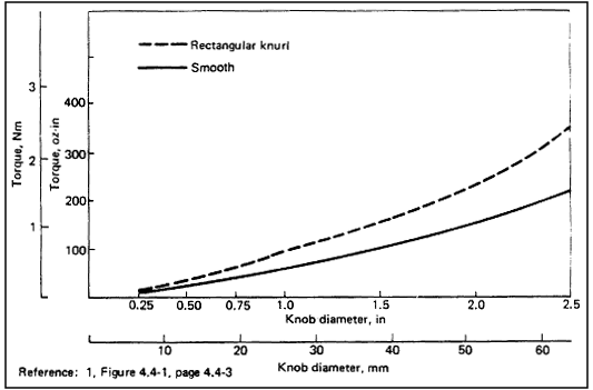
Reference: 1, Figure 4.4-1,
p. 4.4-3; NASA-STD-3000 24
Figure
11.9.2-2 Hand Torque Capabilities When Restrained by One Hand (IVA)
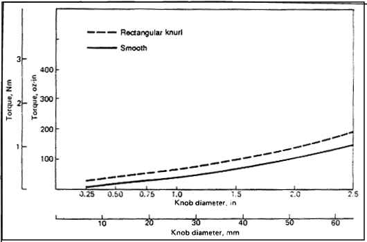
Reference: 1, Figure 4.4-5,
p. 4.4-2; NASA-STD-3000 25
(Refer to paragraph 14.6.3.2,
EVA Fastener Design Considerations, for EVA-unique fastener torquing
capabilities.)
Hand-actuated fasteners need to be durable enough that they can be
actuated by a tool with reasonable care.
Frequency of Use - Select a fastener type that is suited to the frequency
of use. Fasteners used frequently should be very easy to actuate in
a short time to minimize crew workload. Frequently used fasteners must
be durable enough to take repeated actuations without wearing out. Quick
connect/disconnect fasteners, e.g., quarter-turn or half-turn fasteners,
are always preferred in frequent-use applications where low torquing
is suitable. Where multi-turn fasteners are required, it is recommended
that a fastener shall fasten or unfasten in less than ten turns.
d. Clearance and Access - Adequate clearance needs to be provided around
fasteners for the crewmember to obtain hand access, to have adequate
tool clearance, and to have adequate wrenching space. Sockets, extensions,
lever arms, etc., should receive special consideration for access and
clearance. Consider that it might take two hands or a power tool to
manipulate, breakaway, or remove stuck fasteners. Recessed fasteners
should be avoided. Fastener mounting holes should be large enough to
allow starting fasteners without perfect alignment.
e. Bare Hand or Gloved Actuation - When selecting fasteners, either
hand-actuated or tool-actuated, it is necessary to consider whether
the fasteners or the tool will be manipulated by the bare hand or with
a pressurized glove.
f. Safety Considerations - Exposed fasteners need to be selected so
that they will not snag clothing or cause injury to the crewmembers
as they move about. Fasteners and latches should not spring open and
cause injury to the crewmember when the fastener or latch is disconnected.
g. Minimum Number of Fasteners - Minimize the number of fasteners used
in an application.
h. Tool-Actuated
Fastener Head Type - High torque applications should use internal (Allen)
or external hex-head styles.
i. Fastener Replacement - It is necessary to consider how stripped,
worn, or damaged fasteners can be replaced. Avoid fasteners that are
1) an integral part of the equipment (e.g., threaded studs) or 2) countersunk.
j. Dual-Purpose Fasteners - Fasteners which perform a dual purpose
may be used (e.g., a lock handle may be designed to serve as an extra
handhold).
k. Cotter Keys and Safety Wire - The use of cotter keys and safety
wire should be avoided.
l. Fastener Material - It is recommended that for threaded fasteners
that the replaceable component be made of a softer material than the
non-replacement component.
m. Thread Lubrication - The selection of thread lubricants should be
addressed as part of the design process.
n. Thread Fastener Installation/Replacement - Thread fasteners should
be installed with torque limiting tools - these tools should be available
on-orbit.
11.9.3 Fastener Design
Requirements
{A}
This section provides the fastener design requirements.
Paragraph 11.9.3.1 provides general fastener design requirements.
Paragraph 11.9.3.2 provides requirements that
are applicable to hand-actuated fasteners. Paragraph
11.9.3.3 provides requirements that pertain to tool-actuated fasteners.
Paragraph 11.9.3.4 provides the design requirements
that pertain to IVA fasteners.
(Refer to Paragraph 14.6.3.3,
EVA Fasteners Design Requirements, for the EVA-unique design requirements.)
Figure
11.9.2-3 Torque by Knob Size (Values for 5th Percentile Male)
| Knob
diameter |
Rim Surface |
Rectangular knurl
.gif) |
Diamond knurl
.gif) |
Smooth
.gif) |
| cm |
in. |
Ncm |
lb-in. |
Ncm |
lb-in. |
Ncm |
lb-in. |
| 0.3 |
1/8 |
2.3 |
0.2 |
3.4 |
0.3 |
0.3 |
0.03 |
| 0.6 |
1/4 |
8.8 |
0.6 |
7.9 |
0.7 |
2.3 |
0.2 |
| 1.0 |
3/8 |
11.3 |
1.0 |
12.4 |
1.1 |
4.5 |
0.4 |
| 1.3 |
1/2 |
14.7 |
1.3 |
17.0 |
1.5 |
6.8 |
0.5 |
| 1.6 |
5/8 |
22.6 |
2.0 |
20.3 |
1.8 |
9.0 |
0.8 |
| 1.9 |
3/4 |
27.1 |
2.4 |
27.1 |
2.4 |
15.8 |
1.4 |
| 2.2 |
7/8 |
32.8 |
2.9 |
32.8 |
2.9 |
15.8 |
1.4 |
| 2.5 |
1 |
45.2 |
4.0 |
40.7 |
3.6 |
17.0 |
1.5 |
| 3.2 |
1-1/4 |
44.1 |
3.9 |
49.7 |
4.4 |
22.6 |
2.0 |
| 3.8 |
1-1/2 |
63.3 |
5.6 |
59.9 |
5.3 |
38.4 |
3.4 |
| 4.4 |
1-3/4 |
81.4 |
7.2 |
83.6 |
7.4 |
42.9 |
3.8 |
| 5.1 |
2 |
97.2 |
8.6 |
91.5 |
8.1 |
50.9 |
4.5 |
| 5.7 |
2-1/4 |
116 |
10.3 |
116 |
10.3 |
71.2 |
6.3 |
| 6.4 |
2-1/2 |
140 |
12.4 |
131 |
11.6 |
93.8 |
8.3 |
| 7.0 |
2-3/4 |
174 |
15.4 |
173 |
15.3 |
88.1 |
7.8 |
| 7.6 |
3 |
181 |
16.0 |
179 |
15.8 |
94.9 |
8.4 |
| 8.9 |
3-1/2 |
220 |
19.5 |
244 |
21.6 |
147 |
13.0 |
| 10.2 |
4 |
280 |
24.8 |
290 |
25.7 |
164 |
14.5 |
| 11.4 |
4-1/2 |
320 |
28.3 |
330 |
29.2 |
208 |
18.4 |
| 12.7 |
5 |
380 |
33.6 |
392 |
33.8 |
244 |
21.6 |
Reference: 1, Table 4.4-1,
page 4.4-3; NASA-STD-3000 26
11.9.3.1 General
Fastener Design Requirements
{A}
This section provides the fastener design requirements that pertain
to both IVA and EVA applications.
a. Commonalty - The number and diversity of fasteners shall be minimized
commensurate with the structural requirements imposed by the physical
environments.
b. Easily Distinguishable - Where different types of fasteners must
be used, they shall be such that they are readily distinguishable from
each other.
c. Hand-Actuated Fasteners Preferred - Hand-actuated fasteners shall
be given preference over tool-actuated fasteners, provided that size,
location, and structural constraints are met.
(Refer to Paragraph 11.9.3.2, Hand-Actuated
Fastener Design Requirements, for specific requirements.)
(Refer to Paragraph 11.9.3.3, Tool-Actuated
Fastener Design Requirements, for specific requirements.)
d. Other Devices in Lieu of Fasteners - Optimum use shall be made of
mechanical devices (e.g., hinges and tongue-and-slot catches) to minimize
the number of fasteners.
e. Captive Fasteners - All fastener components intended for crew interaction
shall be captive. All replaceable fasteners shall be amenable to loose
parts control and a means of fastener containment and/or restraint shall
be incorporated in the fastener removal/replacement system.
f. Accessibility :
(Refer to Paragraph 11.2.3.6, Tool Access
Design Requirements, for specific tool clearance dimensions.)
1. Location Near Corners - Fasteners shall be located far enough away
from internal corners, wall edges, flanges, etc., that they can be manipulated
with ease.
2. Separation - Fasteners shall be located far enough apart so there
is adequate hand or tool clearance.
3. Location Near Adjacent Equipment - If a component is to be mounted
near other pieces of equipment, fasteners shall be located away from
the edges of the adjacent equipment, obstructions, or surfaces that
will prevent the attachment of tools.
4. Direct Access - Locate fasteners so that they can be actuated without
removing other parts or units first.
5. Access Holes - Covers or shields through which mounting fasteners
must pass for attachment to the basic chassis of the unit shall have
large enough holes for passage of the fastener without precise alignment
(and tool/hand if tool/hand is required to replace).
g. One Handed Actuation - All fasteners shall be designed to be actuated
by one hand.
h. Engagement Status Indication - Incorrect engagement of fasteners
shall be apparent.
i. Multiple Fasteners :
1. Number of Fasteners - When several fasteners are required, the design
shall use the minimum number of the largest size fasteners of identical
type.
2. Arrangement - When several fasteners are used on one item, they
shall be arranged so that the unit can be assembled in only the correct
manner.
j. Safety - Fasteners shall be designed so as to preclude injury to
the crewmember when the fastener is released.
k. Labeling - Appropriate markings shall be placed on fasteners that
can be actuated by either hand or tool .
(Refer to Paragraph 9.5,
Labeling and Coding, for specific considerations and requirements.)
l. Replacement - All fasteners shall be de- signed for on-orbit replacement.
(Refer to Paragraph 11.2.3.2 d., Fastener
Tools, for specific requirements.)
11.9.3.2 Hand-Actuated
Fastener Design Requirements
{A}
In addition to the general fastener design requirements given in
Paragraph 11.9.3.1, IVA and EVA hand-actuated fasteners shall be
designed to the following requirements:
a. One-Handed/Either-Hand Actuation - Hand-actuated fasteners shall
be designed to be actuated by one hand and by either the left or right
hand.
b. Designed for Launch and On-Orbit - Fasteners shall be designed to
meet the launch loads as well as on-orbit loads.
c. Fastener Knobs - Fastener knobs shall be textured.
(Refer to Paragraph 6.3.3, Mechanical
Hazards Design Requirements, for specific safety design requirements.)
d. Quick-Opening Fasteners - Quick-opening captive fasteners shall:
1. Require a maximum of one complete turn to operate (quarter-turn
fasteners are preferred).
2. Require only one hand to operate.
3. Be positive locking in open and closed position.
e. Locking Threaded Fasteners - Hand-actuated threaded fasteners shall
have a locking feature that provides an audible, tactile, or visual
feedback to the crewmember. Such locking features shall assure that
threaded fasteners will not unthread themselves without crew actuation.
f. Pin Fasteners (IVA) :
1. Alignment - Hardware utilizing pin fasteners shall be designed to
accommodate misalignment of holes caused by on-orbit distortions of
primary and secondary equipment.
2. Locking devices - Locking devices used in conjunction with pin fasteners
shall be made accessible and easily visible.
(Refer to Paragraph 14.6.3.3,
EVA Fastener Design Requirements, for EVA use of pin fasteners.)
g. Over-Center Latches :
1. Non-self-latching - Over-center latches shall include a provision
to prevent undesired latch element realignment, interference, or re-engagement.
2. Latch lock - Whenever possible, latch catches shall be spring loaded
to lock on contact, rather than using a positive locking device. If
positive locking is necessary, provide a latch loop and locking action.
3. Latch handles - If the latch has a handle, locate the latch release
on, or near the handle so it can be operated with one hand.
h. Safety Wire
- Safety wires shall not be used on fasteners.
11.9.3.3 Tool-Actuated
Fastener Design Requirements
{A}
In addition to the general fastener design requirements given in
Paragraph 11.9.3.1, IVA and EVA tool-actuated fasteners shall meet
the following design requirements:
(Refer to Paragraph 11.9.3.4, IVA Fastener
Design Requirements, for IVA-specific tool-actuated fastener requirements.)
(Refer to Paragraph 11.2.3, Tool Design Requirements,
for specific requirements for the tools to be used to actuate the tool-actuated
fasteners.)
(Refer to Paragraph 14.6.3.3,
EVA Fastener Design Requirements, for EVA fastener requirements.)
a. Nonstandard Tools - Fasteners requiring nonstandard tools shall
not be used.
b. High-Torque Fasteners (IVA Only) - External hex or external double-hex
fastener heads are preferred and they shall be provided on all machine
screws, bolts, or other fasteners requiring more than 14 Nm (10 ft-lbs)
of torque. Internal wrenching fasteners shall be Allen-head-type fasteners.
c. Low-Torque Fasteners :
1. Hex-type internal grip head, hex-type external grip head, or combination-head
(hex or straight-slot internal grip and hex-type external grip head)
fasteners shall be used where less than 14 Nm (10 ft-lb) of torque is
required.
2. Internal-grip head fasteners shall be provided only where a straight
or convex smooth surface is required.
3. No straight-slot or Phillips-type internal grip fasteners shall
be used.
d. Precision Torquing - When possible, design equipment so that precise
torque on fasteners is not required. Where precise torque or preload
is required, use fasteners that incorporate torque-indicating features
or that will mate with appropriate on-board torquing tools.
e. Torque Labeling - When fastener torquing to specifications is required,
an instructional label shall be provided in reasonable proximity to
the fasteners.
(Refer to Paragraph 9.5,
Labeling and Coding, for specific requirements.)
f. Number of Turns - When machine screws or bolts are required, the
number of turns and the amount of torque shall be no more than necessary
to provide the required strength.
g. Fastener Head Length (IVA Only) - Fastener heads shall be as short
as possible so they will not snag personnel clothing or equipment.
h. Left-Hand Threads - Left-hand threads shall not be used unless system
requirements demand them; then identify both the bolts and nuts clearly
by use of markings, shape, color, etc.
i. Locking
- Threaded fasteners shall incorporate features that allow them to be
locked so that they will not unthread without using a tool.
j. Hand Tool Operable - All fasteners installed with power tools shall
be removable with a hand-operated tool.
11.9.3.4 IVA Fastener
Design Requirements
{A}
In addition to the fastener design requirements given in
Paragraphs 11.9.3.1 through 11.9.3.3, all IVA fasteners shall meet
the following requirements:
(Refer to Paragraph 14.6.3.3,
EVA Fastener Design Requirements, for EVA-unique requirements.)
a. Fastener Lubrication - IVA fasteners that require lubrication shall
use an approved lubricant or plating material.
b. Cadmium Plating - Cadmium-plated IVA fasteners shall not be used.
c. Wing-Head Fasteners - Wing-head IVA fasteners shall fold down and
be retained flush with surfaces so they will not snag personnel, clothing,
or equipment.
d. Cotter Keys :
1. Fit - Keys and pins shall fit snugly without requiring being driven
in or out using a tool.
2. Large heads - Cotter keys shall have large heads for easy removal
by hand.
3. Cotter keys shall not be used EVA.
e. Access - Minimal requirements for access and/or clearance areas
for tool-actuated fasteners shall be as shown in
Figure 11.2.3.6-1 and Figure 11.2.3.6-2.
(Refer to Paragraph 11.2.3.6, Tool Access
Design Requirements, for specific access requirements.)
f. Tool-Actuated Fastener Head Types - In addition to the general tool-actuated
fastener design requirements given in Paragraph
11.9.3.3, the following IVA-specific tool- actuated fastener selection
requirements shall apply: (NOTE: Special mission or program requirements
may create the need to use other types of fastener heads than those
listed below.)
1. Fastener heads directly exposed to crew impact shall meet the requirements
for burrs, edges, and sharp corners, or shall be provided with protective
covers or they shall be flush with surface.
(Refer to Paragraph 6.3.3, Mechanical
Hazards Design Requirements.)
2. Fastener heads not directly exposed to crew impact within habitability
and stowage areas shall be internal or external hex head.
g. Anti-Seize and Locking Compounds - Anti-Seize and locking compounds
shall not be used on fasteners.
11.9.4 Example Fastener
Design Solutions
{O}
Refer to Reference 155,
Section 3.2.2.2, for descriptions and evaluations of the hand-operated
fasteners used on the Skylab Program.
11.10
CONNECTORS
{A}
{A}
Electrical, fluid, gas, structural, and optical connectors are discussed
in this section. Included are requirements for connector selection,
identification, alignment, spacing, accessibility, and protection of
equipment. 
(Requirements for EVA connectors are detailed in
Paragraph 14.6.3.)
(See Paragraph 11.14, Cable
Management, for electrical cable information.)
(Refer to Paragraph 9.5,
Labeling and Coding, for additional connector coding and identification
requirements.)
11.10.2 Connector
Design Considerations
{A}
Connectors are essential to the assembly and disassembly of equipment,
both during the construction and checkout phase and later during maintenance.
Unfortunately, connectors are not totally reliable and most are susceptible
to damage. Hence, connectors should be used only where needed. Connectors
should be selected, designed, and mounted for:
a. Fast and easy maintenance operations.
b. Easy removal and replacement of components and units.
c. Minimal time to setup, test, and service equipment.
d. Minimum danger to personnel and equipment during mating or demating
of connectors due to content spills, electrical shocks, or damage from
the release of stored mechanical energy.
e. One-hand operation where possible.
It should be noted that single rows of electrical connectors normally
provide best access. Multiple rows of connectors are not desirable,
but if required, the connectors should be staggered.
(Refer to Figure 11.10.3.6-2 Preferred
Spacing of Staggered Rows of Connectors.)
11.10.3 Connector
Design Requirements
{A}
All types of IVA and EVA connectors shall meet the following general
requirements:
a. One-Handed Operation - All connectors, whether operated by hand
or tool, shall be designed so they can be mated/demated using one hand.
For connector design torque values refer to Paragraph
11.9.
b. Accessibility - It shall be possible to mate/demate or replace individual
connectors without having to remove or replace other connectors.
(Refer to Paragraph 14.6.4.3,
EVA Connectors Design Requirements, for EVA-unique connector design
requirements.
11.10.3.1 Fluid
Connectors Design Requirements
{A}
All IVA and EVA liquid and gas connectors shall be designed to meet
the following requirements:
a. Fluid Line Connectors - All brazed or welded gas and liquid lies
shall be provided with convenient-to-use, permanently installed connectors
that permit on-orbit maintenance.
(Refer to Paragraph 12.3.1.4,
Removal, Replacement and Modularity Design Requirements, for fluid and
gas line isolation valve requirements.)
b. Indication of Pressure Flow - All liquid and gas lines shall be
provided with a positive indication of the gas pressure/fluid flow to
verify that the line is passive before disconnection of connectors.
Quick Disconnects (QDs) that are designed to be operated under pressure
will not require pressure/flow indications.
c. Fluid Loss- Liquid and gas connectors shall be designed to minimize
escape or loss of fluids, particularly any toxic materials, during connect
or disconnect operations.
11.10.3.2 Electrical
Connectors Design Requirements
{A}
All IVA and EVA electrical connectors shall comply with the following
general requirements in addition to the requirements in Paragraph
6.4.3.3.
(Refer to Paragraph 14.6.4.3,
EVA Connectors Design Requirements, for additional EVA-unique electrical
connectors requirements.)
a. Ease of Disconnect - Electrical connector plugs shall require no
more than one turn to disconnect or some other quick disconnect design
shall be provided.
b. Self-Locking - Electrical connector plugs shall provide a self-locking
safety catch.
c. Access - Electrical connectors and cable installations shall be
designed with sufficient flexibility, length, and protection to permit
disconnection and reconnection without damage to wiring or connectors.
(Refer to Paragraph 11.14.3, Cable Management
Design Requirements, for other related requirements.)
d. Arc Containment - electrical connector plugs shall be designed to
confine/isolate the mate/demate electrical arcs or sparks.
(Refer to Paragraph 6.4.3, Electrical
Hazards Design Requirements, for specific electrical safety requirements.)
e. Contact Orientation - All efforts shall be made to arrange contacts
within connectors such that when the connectors are demated there will
be no voltage potential on exposed male pins. Refer to
Paragraph 6.4.3.7.
f. Contact Protection - All demated connectors shall be protected against
physical damage and contamination.
11.10.3.3 Structural
Connectors Design Requirements
{A}
All IVA and EVA structural connectors shall meet the following requirements:
a. Alignment Provisions - All structural connectors shall incorporate
alignment features.
(Refer to Paragraph 11.10.3.5, Connector
Identification/Alignment Design Requirements, for specific requirements.)
b. Soft Latching - All structural connectors shall provide the capability
to soft-latch prior to full firm connection or full release.
c. Lock Indication - All structural connectors will provide an indication
of positive locking.
11.10.3.4 Optical
Connectors Design Requirements
{A}
All fiber optic connectors shall be designed so that proper geometric
alignment and abutment maintains signal fidelity.
(Refer to Paragraph 11.10.3.5, Connector
Identification/Alignment Design Requirements, for specific requirements.)
11.10.3.5 Connector
Identification/Alignment Design Requirements
{A}
Connectors shall be selected, designed, and installed so they cannot
be mismated or cross-connected. The following requirements are applicable:
a. Connector Shape - Use connectors that are clearly different and
physically incompatible when lines differ in content (i.e., different
voltages, liquids, gases).
b. Alignment Provisions:
1. Mating connectors shall be provided with aligning pins or equivalent
devices to aid in alignment and to preclude inserting in other than
desired orientation.
2. If aligning pins are used on electrical connectors, they shall extend
beyond the plug's electrical pins to ensure that alignment is obtained
before the electrical pins engage.
c. Keying:
1. Symmetrical arrangement of aligning pins or keys shall be avoided
to prevent connectors from being mismated.
(See Figure 11.10.4-2, Electrical
Connector Keys and Keyways, and Figure
11.10.4-3, Arrangement of Guide Pins.)
2. The mechanical keys shall prevent incorrect connections with other
accessible connectors, plugs, or receptacles.
d. Alignment Marks:
1. Alignment marks shall be applied to mating parts if the proper interface
orientation is not obvious by virtue of geometry.
2. The marks shall consist of a straight line of a width and length
appropriate to the size of the items and shall be located so as to be
easily seen by the crewmember both before and after mating/demating
operations.
e. Coding:
1. Both halves of mating connectors shall display a code or identifier
unique to that connection.
2. Labels or codes on connectors and associated items shall be located
so they are visible when connected or disconnected.
(Refer to Paragraph 9.5.3, Labeling
and Coding Design Requirements, for specific requirements.)
f. Pin Identification-Each pin shall be clearly identified in each
electrical plug and each electrical receptacle.
g. Orientation-Grouped plugs and receptacles shall be oriented so that
the aligning pins or equivalent devices are in the same relative position
(i.e., all keyed connectors oriented the same direction-key up).
h. Loose Hoses or Cables:
1. If the connectors on the ends of a loose electrical cable or fluid
hose are not identical, each end shall be uniquely identified to prevent
improper usage.
2. The loose ends of hoses and cables shall be restrained to prevent
them from floating out of reach and to avoid injury to crewmembers and
damage to equipment.
11.10.3.6 Connector Arrangement Design Requirements
{A}
All types of IVA and EVA connectors shall comply with the following
arrangement and spacing requirements:
(Refer to Paragraph 14.6.4.3,
EVA Connectors Design Requirements, for EVA-specific connector arrangement
and spacing requirements.)
a. Hand Access-Connectors shall be spaced far enough apart so that
they can be grasped firmly for connecting and disconnecting
b. Adjacent Connectors or Obstructions-Space between a connector and
any adjacent obstruction shall be compatible with the size and shape
of the plugs.
c. Single Rows-Connectors in a single row which require removal and
replacement by the crew (IVA) shall be a minimum of 25 mm (1 in.) apart
(edge-to-edge) for hand access during alignment and insertion. A separation
of 41 mm (1.6 in.) is required for EVA and preferred for IVA. (See
Figure 11.10.3.6-1.)
d. Staggered Rows-Staggered rows of connectors shall be a minimum of
64 mm (2.5 in.) apart-IVA and EVA, (see
Figure 11.10.3.6-2).
e. Tools-If a tool is used, the hand access clearance is still required
to facilitate initial alignment by hand.
Figure
11.10.3.6-1 Preferred Spacing of Single Row of Connectors
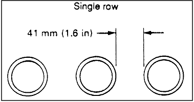
Reference: 1, Figure 3.6-5,
p. 3.6-5; NASA-STD-3000 28
Figure
11.10.3.6-2 Preferred Spacing of Staggered Single Rows of Connectors
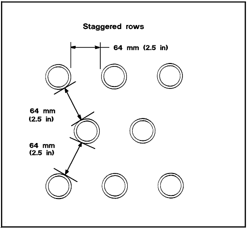
Reference: 1, Figure 3.6-6,
p. 3.6-5; NASA-STD-3000 29
11.10.4 Example Connector Design Solutions
{A}
The following examples show methods that should be considered to identify,
code, align, and mark electrical connectors and receptacles.
a. Coding-Methods of coding connectors and mating plugs or receptacles
are shown in Figure 11.10.4-1. Discrete
nomenclature of alphanumeric coding is preferred to color coding.
b. Locating Labels-Alphanumeric coding of electrical connections plugs
and receptacles (Figure 11.10.4-1) are
located so they are visible when connected or disconnected.
c. Keys and Keyways - Correct and incorrect methods of providing keys
and keyways on electrical connectors are shown in
Figure 11.10.4-2.
d. Alignment Pins-Correct and incorrect methods of providing alignment
pins on electrical connectors are shown in
Figure 11.10.4-3.
e. Alignment Marks-Alignment marks on electrical connector plugs and
interfacing receptacles are shown in Figure
11.10.4-4. They are so located as to provide the crewmember with
line-of-sight access during insertion.
Reference: 15, Figure
5; NASA-STD-3000 30
Figure
11.10.4-2 Electrical Connector Keys and Keyways
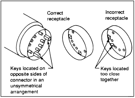
Text:
The Correct receptacle has keys
located on opposite sides of connector in an unsymmetrical arrangement.
The Incorrect receptacle has keys
located too close together. |
Reference: 19, Chapter
2, Section 26, p. 9; NASA-STD-3000 31
| Use this |
Not this |
This is a symmetrical pin arrangement with non-symmetrical guide
pin arrangement
.gif) |
This is a totally symmetrical pin and guide pin arrangement
.gif) |
Reference: 19, Chapter
2, Section 26, p. 9; NASA-STD-3000 32
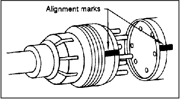
Reference: 19, Chapter
2, Section 26, p. 9; NASA-STD-3000 33
11.11
WINDOWS
{A}
11.11.1 Introduction
{A}
This section provides design considerations, requirements, and examples
for window optical characteristics, visual protection for the window
users, physical protection of the window interior and exterior surfaces,
and window maintenance.
(Refer to Paragraph
8.11, Window Integration, for design considerations and requirements
pertaining to window location with respect to the overall architecture
of the space module.)
(Refer to Paragraph 9.2.5.1, Window
Workstation, for design requirements pertaining to integration of windows
with controls, displays, and other man/machine interfaces.)
11.11.2 Window Design Considerations
{A}
The following window design considerations represent selected background
information that should be considered in window design. See Reference
178 for more comprehensive treatment of these considerations.
11.11.2.1 Optical Characteristics Design Considerations
{A}
Window transmissivity is a critical design parameter because some visual
tasks require perception of very small, faint sources of light. Visual
perception decreases with decreased window transmissivity. The window
transmissivity must be constant across its entire surface to prevent
distortion of viewed objects. The glass must be free of inclusions (e.g.,
air bubbles, foreign particles). These glass imperfections can 1) cause
the viewer to focus improperly on objects and 2) cause glare which can
also degrade visual perception.
The line of sight (LOS) of the viewer looking through a window system
of multiple glass surfaces, may be altered by a variety of factors;
nonparallel multiple glass surfaces create a prism effect causing line
of sight deviation wherein the visual judgment of target motion normal
to the LOS may be in error. Each surface of a window panel must be flat
and parallel so that it does not contain an astigmatic error in which
the observer perceives out-of-focus images. Since the eye cannot focus
at two distances at the same time, it well likely seek and intermediate
focus. This results in blurring or distortion which causes visual fatigue.
Reflections produced by internal or external light sources can interfere
with visual identification and other judgments of luminous targets and
cause eye fatigue. Anti-reflection coatings, polarizing filters, or
glare screens can help reduce these reflections.
In general, even though the optical qualities of windows should be
dictated by the various uses to which they will be put, it is reasonable
to design into them as high optical quality as is affordable in anticipation
of future experimental and other mission requirements.
11.11.2.2 Visual Protection Design Considerations
{A}
Internal and external shutters or shades have been employed on previous
manned space vehicles to protect the crewmember from the high intensity
sunlight, to reduce glare, and to reduce ambient lighting where low
light levels were needed for operational tasks or for sleep periods.
The external shutters also act as protection from micrometeorites and
other potential external sources of damage or contamination, thus preserving
the life and quality of the window.
Filters and coatings are used to protect the observer's eyes and exposed
skin surfaces from harmful infrared or ultraviolet radiation. Filters
may be required to protect the eyes from laser light. Applicable laser
light safety criteria should be adhered to so that inadvertent admittance
of laser light through the windows is prohibited.
(Refer to Paragraph 5.7.3.1.4,
Non-Ionizing Radiation Protection Design Considerations, and
Paragraph 5.7.3.2.1, Non-Ionizing Radiation Exposure Limits, for
specific laser safety considerations and requirements.
11.11.2.3 Physical Protection Design Considerations
{A}
There are many sources of natural and manmade external window surface
contaminants. Natural sources of contamination include micrometeoroids,
cosmic particles, and electrons. Manmade sources of contamination include
propellants, ECLSS outgassing, sealant outgassing, fluid leaks, waste
dumping, atmosphere leakage, and EVA glove and boot prints.
Between-pane contamination may result from outgassing of gaskets or
from moisture that is not removed during the window assembly process.
Provision for early detection and removal of moisture from spaces between
multiple window panes should be provided, particularly for long-duration
missions.
Window surface contamination sources inside the space module include
breath condensation, finger prints, body oils, urine, skin, and bacteria.
These window surface contaminants scatter sunlight into the observer's
eyes and produce glare that reduces the crewmembers ability to detect
faint visual targets. The space module design should prevent or minimize
these sources of contamination whenever technically and economically
feasible. Anti-fogging coatings, heated glass, sacrificial (i.e. removable)
surfaces, and protective covers are some of the ways that contamination
can be prevented.
Window flaws and cracks can grow imperceptibly until they reach a catastrophic
magnitude. A means should be provided for performing continuous window
integrity inspections.
11.11.2.4 Window Maintenance Design Considerations
{A}
Due to the external and internal contaminants and accidental mechanical
damage, contingency window maintenance must be provided.
Window surface cleaning materials and processes must be designed to
preserve the optical qualities of the window by not scratching or staining
the surfaces. Polishing/buffing operations are not recommended since
they are likely to do more damage than good.
Removable, transparent window covers (i.e., sacrificial surfaces) should
be considered as a means to expedite the window maintenance. These disposable
covers would be designed to absorb most of the mechanical damage or
staining that cannot otherwise be avoided.
The possibility of replacing one or more window panes on-orbit should
be considered for permanently orbiting space modules. Techniques for
accomplishing this replacement operation should not entail depressurization
of the module.
11.11.3 Window Design
Requirements
{A}
This section provides the design requirements for the optical characteristics,
visual protection for the window user, physical protection of the window
panes and window maintenance.
The following optical characteristics requirements shall apply to window
and viewport design in order that no visible distortions or optical
defects shall be detectable by a person possessing 20/20 acuity within
the normal viewing envelope under operational lighting conditions.
(Refer to Paragraph 8.11.3, Window
Integration Design Requirements, for window architectural requirements.)
(Refer to Paragraph 9.2.5.1.2,
Window Workstation Design Requirements, for additional requirements
when the window will be used in conjunction with controls, displays,
restraints, etc.)
11.11.3.1 General Viewing Window Requirements
{A}
11.11.3.1.1 Window Size
{A}
a. Hatch windows shall be minimum of 20.3 cm (8 in.) diameter.
b. General area windows shall be a minimum of 50.8 cm (20 in.) in height
and width or diameter.
11.11.3.1.2 Surface Reflections
{A}
a. Windows shall be designed such that specular reflectance from each
air-glass interface shall not exceed 1.5 percent for light incident
on the surface.
b. When anti-reflection coating are applied to windows, they shall
not cause resolution degradation exceeding .007 mr (1.5 arc seconds).
11.11.3.1.3
Optical Characteristics
{A}
At completion of manufacture, the window panes, with all accepted coatings
shall meet the following optical requirements within the clear viewing
area.
a. Deviation at any point on the window panes shall not exceed 1.45
mr (5 arc minutes). Tempered window panes shall not exceed 2.9 mr (10
arc minutes).
b. Distortion of all types of window materials shall not exceed a plane
slope of 1:24.
c. Haze of the uncoated window pane for all thicknesses shall not be
greater than 2%.
d. Warp and Bow-All glass window panes shall not exhibit warp or bow
greater than 0.030 inch per linear foot of the glass.
e. Surface Parallelism-The surface parallelism between multipanes of
window systems shall not exceed 0.58 mr (2 arc minutes) from inner surface
to outer surface of the complete assembly.
{A}
Each pane shall be manufactured so that when multipanes for window
group the following shall be met.
a. Infrared-The
optical density shall be greater than one for wavelengths between 850
and 1000 nanometers (less than 10%). For wavelengths greater than 1000
nanometers, the transmittance shall be less than 8%.
b. Ultraviolet-The
optical density shall be greater than three for wavelengths between
320 and 280 nanometers. The optical density shall be greater than four
for wavelengths between 220 and 280 nanometers.
c. Visible-In
the region between 420 and 800 nanometers, the transmittance through
a window composite shall not be less than 70%. The transmissivity shall
not vary more than 25% for incident angles between the window surface
and LOSs ranging from 30 to 60 degrees.
{A}
The surface of each window pane shall be such that digs shall not exceed
0.122 cm (0.050 inches) diameter and scratches shall not exceed 0.0015
cm (0.0006 in.) deep. Chips shall not exceed 0.078 cm (0.032 inch.)
in surface penetration and 0.04 cm (0.016 inch.) in thickness.
{A}
The maximum number of open seeds per surface shall not exceed three
and shall not exceed 0.1225 cm (0.050 inch) in diameter or exceed a
total number of 5 per cubic inch.
a. Striae - Striae shall not exceed a diameter of 0.2 cm (0.080 inch)
and are limited to no more than 2 square inch.
b. Inclusions-Inclusions shall not exceed 0.37 cm (0.15 inch) in diameter
and more than 1 per cubic inch.
11.11.3.1.7
Visual Protection Design Requirements
{A}
The window design shall meet the following requirements:
a. Sun Shields/Shades
1. Sun Shields - All viewing windows shall be provided with crew-operated,
opaque sun shields which are capable of restricting all sunlight from
entering the habitable compartments.
2. External Sun Shades - If external shades are provided there shall
be a means to reposition by the window user.
b. Heat Rejection - The sun shade, whether internal or external, shall
be capable of rejecting radiant energy away form the window assembly.
Window design shall be coordinated with other shielding protection
design to achieve less than or equal to allowable radiation dosages
given in these paragraphs.
c. Visual Protection - Visual Protection Requirements are met by the
requirements in Paragraphs 11.11.3.1.4.a
and 11.11.3.1.4.b Optical Density.
11.11.3.1.8 Physical Protection Design Requirements
{A}
Window design shall meet the following surface contamination and breakage
requirements which are imposed to ensure that the windows can be used
for the intended observation functions and that the module pressure
integrity is maintained:
a. External Surface Contamination Protection - Window design shall
take into account all sources of external contamination and shall provide
a means for cleaning or replacing when degradation exceeds optical transmissivity
requirements.
b. Between-Pane Contamination Protection - Window design shall take
into account all sources of contamination that can occur between the
transparency panes and shall provide a means of preventing optical degradation
due to these contaminants.
c. Internal Surface Contamination Protection - Window design shall
take into account all sources of internal surface contamination and
provide a means for preventing or minimizing optical degradation due
to these contaminants.
1. Anti-fogging - All innermost panes shall be designed for anti-fog
protection.
2. Inner Pane Coatings - The innermost pane shall have no coatings
except for anti-reflective coatings.
d. Impact Load Protection - The window assembly shall be capable of
withstanding a blunt object impact load of 550 N (125 lb) from any angle
of incidence.
e. Protection Covers - Removable or extractable protection covers shall
be provided where the window assembly does not meet crew and equipment
impact load criteria or the launch and reentry pressure profiles.
f. Retractable External Protective Covers - If external protective
covers are opaque, then IVA controls shall be provided with a backup
EVA capability to override the IVA system.
11.11.3.1.9 Window Maintenance Design Requirements
{A}
The following window maintenance requirements are imposed to minimize
the crew workload and prevent degradation of the optical qualities of
the windows:
a. Window Servicing - Equipment and supplies shall be provided for
efficient contingency window cleaning.
b. Protective Covers - Where surface scratching, pitting, or staining
cannot be prevented by other means, removable window protective surfaces
shall be provided.
c. Window Replacement - Window assemblies shall be designed to eliminate
the need for depressurizing modules in order to replace window panes
or the entire window assembly.
11.11.3.2 Scientific
Window Design Requirements
{A}
This section defines the requirements for a scientific window for special
photographic and scientific investigation.
a. Aperture Diameter-The window shall be a single pane or multipane
system with a minimum aperture diameter of 55.9 cm (22 inches).
b. View - The window shall be located to provide unobstructed viewing.
11.11.3.2.1
Window Glass Requirements
{A}
These specifications apply to scientific viewing windows, for the pressure
pane, the backup pane and the meteoroid debris protective pane. The
inside protective pane(s) shall be removable for viewing where they
do not meet the optical requirements and are not required for scientific
investigations (See Paragraphs 11.11.3.2.3
and 11.11.3.2.4).
{A}
a. Window Pane Material - the window panes (glass) shall be fabricated
from optical quality fused silica or equivalent.
b. Inclusions - The silica (glass) shall meet Inclusion Number (Class)
0 as defined in MIL-STD-174B; i.e., seeds and bubbles, to the extent
that the total bubble and seed cross section per 100 cubic cm (6.1 in3
) volume as viewed normal to the surface shall be less than 0.03 mm2
(0.00005 in2).
c. Homogeneity - The index of refraction as measured normal to its
surface of the glazing shall not show a variation greater than 3 X 10⁻⁶
over the entire sensing unit viewing area.
d. Birefringence - Birefringence shall be kept to less than 6 nm/cm
over the entire sensing unit viewing area.
e. Veiling Glare - The complete single window glazing shall not contribute
more than 2% veiling glare to the sensing systems.
{A}
a. Wavefront Error - The RMS wavefront variation through each multipane
window system shall not exceed 1/10 of a light wavelength of 632.8 nm
(helium neon) over any 16.5 cm (6.5 in) diameter aperture within the
clear viewing area, obtained after all necessary optical coatings have
been applied. This specification shall apply when viewing through the
window from normal through 30 degrees off normal to the viewing surface
in any axis.
b. Surface Finish - The surface finish shall be polished to meet or
exceed the requirements of a scratch-dig standard of 60-40 as described
in MIL_0-13830A. The surface roughness shall be no greater than 10 angstroms
remote manipulating system before coating. The roughness shall be measured
across two perpendicular diameters.
c. Wedge - Deviation of the transmitted beam shall not exceed 3.5 arc-seconds
in any direction through a single pane.
d. Parallelism Between Panes - Adjacent panes of a multipane window
shall be parallel between 0.1 degree to 3 degrees. The innermost and
outermost panes of a window system shall not be more than 3 degrees
form parallel; this requirement shall not be met by matching tilted
panes.
e. Grinding and Polishing Sequence - Each optical surface will be polished
using a control grind schedule wherein the material is removed to a
depth equal to 3 times the diameter of the previous grit size through
the polish operation. See Figure
11.11.3.2.1.2-1 for example sequence.
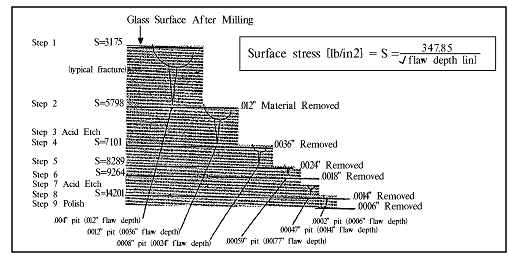
Surface stress [lb/in2] =
S = 347.85/ √ flaw depth [in.]
| Step |
Operation |
Abrasive |
Average Particle (inches) |
Material Removal (Specified in.) |
Surface Strength PSI |
| 1 |
Milling |
150 Grit Diamond |
0.004 |
|
3175 |
| 2 |
Coarse Grind |
Aluminum Oxide |
0.0012 |
0.012 min |
5798 |
| 3 |
Acid Etch |
|
|
|
|
| 4 |
Fine Grind |
Aluminum Oxide |
0.0008 |
0.0036 min |
7101 |
| 5 |
Fine Grind |
Aluminum Oxide |
0.00059 |
0.0024 min |
8268 |
| 6 |
Fine Grind |
Aluminum Oxide |
0.00047 |
0.0018 min |
9264 |
| 7 |
Acid Etch |
|
|
|
|
| 8 |
Fine Grind |
Aluminum Oxide |
0.0002 |
0.0014 min |
14201 |
| 9 |
Polish |
Cerium Oxide |
0.000055 |
0.0006 min |
|
| 10 |
see below * |
Aluminum Oxide |
0.00047 |
|
|
| * Required for clean-up of the polish particles
left on the acid etched edge surfaces. Material removed should
be minimum necessary for clean-up. |
|
NASA-STD-3000 450
f. Edges and Chamfers - All edges and chamfers shall be polished to
relieve stresses caused by grinding. As these are not optical surfaces,
a minimum of orange peel is permissible and may be felt-polished. However
no chips shall be allowed.
g. Residual Stress - The manufacturing process shall be such that when
polished, the window pane shall contain no residual stresses of flaws
introduced during processing.
{A}
Each pane shall be manufactured so that when multipanes form a window
system, the following transmittance shall be met. Transmittance through
the window system at incidence angles from 0 degrees to 30 degrees shall
be as follows:
a. 1200 to 300 nm: 50% minimum.
b. 300 to 400 nm: 60% minimum.
c. 400 to 450 nm: 70% minimum.
d. 450 to 700 nm: 85% minimum.
e. 700 to 900 nm: 60% minimum.
f. 900 to 1200 nm: 40% minimum.
{A}
The reflectance of the window shall be less than 2 percent from a wavelength
of 450 nanometers to 900 nanometers. If an electro-conductive coating
is used, the reflectance shall be less than 2% for wavelengths of 400
nanometers to 700 nanometers and less than 4% for wavelengths of 700
nanometers to 900 nanometers. These requirements shall apply for incidence
angles from 0 degrees to and including 15 degrees from normal.
11.11.3.3 Visual
Protection Design Requirements
{A}
The window design shall meet the following requirements:
a. Sun Shields/Shades:
1. Sun shields-All viewing windows shall be provided with crew-operated,
opaque sun shields capable of restricting all sunlight from entering
habitable compartments.
2. External sun shades repositioning-If external shades are designed
to cast a shadow over a window, they shall be provided with a means
to be remotely repositioned by the window user.
b. Radiation Protection:
1. Infrared-The maximum transmissivity of infrared shall be no more
than 10% (density = 1) in the range of 800 to 1200 nm.
2. Ultraviolet-The maximum transmissivity of ultraviolet shall be no
more than 0.001% (density = 10E-5) in the range of 200 to 300 nm.
3. Heat rejection sun shade, whether internal or external, shall be
capable of rejecting radiant energy away from the window assembly.
(Refer to Paragraph 5.7.2.2, Ionizing
Radiation Design Requirements, for specific ionizing radiation exposure
limits.)
(Refer to Paragraph 5.7.3.2, Nonionizing
Radiation Design Requirements.)
4. Window design shall be coordinated with other shielding protection
design to achieve less than, or equal to, the allowable radiation dosages
given in these paragraphs.
c. Optical Filters-Optical filters shall be provided to meet visual
protection requirements if operational functions require light transmissivity
in excess of the requirements given in item b, above.
11.11.3.4 Physical Protection Design Requirements
{A}
Window design shall meet the following surface contamination and breakage
requirements which are imposed to ensure that the windows can be used
for the intended observation functions and that the module pressure
integrity is maintained:
a. Physical Protection Design Requirements - Window design shall meet
the following surface contamination and breakage requirements which
are imposed to ensure that the windows can be used for the intended
function.
b. Surface Contamination Protection - Window design shall take into
account all sources of external between pane, and internal contamination
and shall provide a means for cleansing or replacing when degradation
exceeds optical transmittance requirements. Scientific windows shall
have an external cover that shall be closed except when these windows
are in use, and shall have an internal transparent removable cover to
protect the internal surface form scratches, smudges and protect the
crewmembers' eyes form UV and IR transmittance. The removable cover
shall be designed such that its removal is evident to all crewmembers
within the module.
c. Protective Cover - Removable or retractable protective covers shall
be provided where the window assembly does not meet crew and equipment
impact load criteria.
d. Retractable External Protective Covers - If external protective
covers are opaque, then IVA controls shall be provided with a backup
EVA capability to override the IVA system.
e. Impact Load Protection-The window assembly shall be capable of withstanding
a blunt object impact load of 550 N (125 lb.) from any angle of incidence.
11.11.3.5 Window
Maintenance Design Requirements
{A}
The following window maintenance requirements are imposed to minimize
the crew workload and prevent degradation of the optical qualities of
the windows:
a. Window Servicing - Equipment and supplies shall be provided for
efficient contingency window cleaning.
b. Protective Covers - Where surface scratching, pitting, or staining
cannot be prevented by other means, removable window protective surfaces
shall be provided.
c. Window Replacement - Window assemblies shall be designed to eliminate
the need for depressurizing modules in order to replace window panes
or the entire window assembly.
(Refer to Section 12.0, Design for Maintainability,
for general and specific maintainability design considerations and requirements.)
11.11.3.6 Window Glass Systems
{A}
11.11.3.6.1 Other Windows
{A}
Windows of a shape other than round shall have a clear viewing aperture
that meets the optical specifications of Paragraph
11.11.3.2.1.2 over an area as large as is consistent with the shape
of the window and the structural mounting requirements. This shall be
a circle up to 20 inches in diameter.
11.11.4 Example Window Design Solutions
{A}
Example window designs from previous US, ESA, and Soviet manned spacecraft
are given in References 155
(Section 3.2.7.2),178, and JSC 32003, Space Station Viewport Study.
11.12
PACKAGING
{A}
11.12.1 Introduction
{A}
This section provides the design considerations, requirements, and
examples for the packaging used for IVA and EVA consumables, spare parts,
experimental specimens, etc.-anything that requires a protective envelope
not directly provided by a stowage system.
Note: This section does not cover the topic of equipment packaging.
Refer to Paragraph 11.3, Drawers and
Racks; Paragraph 11.4, Closures and
Covers; and Paragraph 11.5,
Mounting Hardware, for equipment packaging considerations and requirements.
All packaging must be designed in conjunction with the stowage system.
Refer to Paragraph
10.12, Stowage Facility, for stowage design considerations and requirements.
Food packaging is covered as a special topic in
Paragraph 10.5.3.3, Food Packaging and Stowage Design Requirements,
in the section on the galley.
11.12.2 Packaging Design Considerations
{A}
Packaging design must consider the following factors:
a. Physical Environments - The packaging must be effective under various
combinations of the following physical environmental conditions:
-Temperature
-Humidity
-Vacuum
-Acceleration
-Vibration
-Ambient atmosphere gases and trace contaminants
-Atmospheric pressure
-Light
-Radiation
-Handling by hand
-Long-term use
b. Physical/Chemical Properties-The packaging must be designed to resist
the physical and chemical properties of the contents:
-Consistency
-Fluid, gaseous, or solid state
-pH
-Moisture content
-Microbiological factors
-Fat content
-etc.
In addition, the packaging envelope must be designed to provide the
appropriate microenvironment for the contents. For example, if the package
is for live specimens, it must provide the necessary life support interface
provisions, e.g., ventilation. If the contents need to be delivered
in a pressurized form, the package must be designed to meet the interior
pressure.
Packaging also protects the environment from the contents. For example,
deceased experimental animals must be packaged so that microbiological
contaminants are not released into the space module atmosphere. Contents
must not leak out of the container and cause surface or atmospheric
contaminations.
c. System Engineering Considerations-All packaging designs must take
into account system engineering factors such as weight and volume constraints.
Packaging should be standardized as much as is feasible. Shelf life
from the time of packaging to the time of use must always be considered.
The packaging design must be integrated with stowage, transportation,
restraints, and processing equipment.
d. Sizing - Package size should be determined by taking into account
the rate of usage of the contents, the ease of handling, and the size
of the processing equipment with which the package interfaces.
e. Mobility Aid Interfaces-If the size or shape of the package is such
that a tether, removable handle, or other type of mobility aid will
be used, the package should be designed with suitable attachment interfaces.
f. Contamination-The packaging material should be selected to avoid
introducing contamination hazards into the space module environment.
11.12.3 Packaging
Design Requirements
{A}
All IVA and EVA packaging shall meet the following design requirements:
a. Compatible With Stowage-All packaging form must conform the stowage
space available.
(Refer to Paragraph 10.12.3, Stowage
Facility Design Requirements, for specific requirements.)
b. Compatible With Environments-All packaging must be able to resist
physical environment exposure to which it will be exposed during ground
handling, ground and air transportation and launch, on-orbit and (if
returnable) entry operations.
c. Compatible With Contents-All packaging must be able to resist the
physical characteristics of its contents for the maximum time duration
for which the contents must be packaged.
d. Compatible With Trash Disposal System-All non-reusable packaging
must be compatible with the trash collection and disposal system.
(Refer to Paragraph 10.11.3, Trash
Management Facility Design Requirements, for specific requirements.)
e. Packaging Restraint-Provide means for physically attaching or restraining
the package at all locations where the package may have to be temporarily
placed during use.
f. Labeling-All packages shall be clearly labeled as to their contents.
(Refer to Paragraph 9.5.3.1.9,
Stowage Container Labeling Design Requirements, for specific labeling
requirements.)
g. Inventory Control Compatibility-All packages shall be designed to
incorporate the coding features required by the inventory control system.
(Refer to Paragraph 13.3.3, Inventory
Control Design Requirements, for specific requirements.)
h. Ease of Use:
1. All packaging shall be designed to be usable without extensive manipulation
of the packaging materials.
2. All packaging shall be designed provide efficient and convenient
means of opening and where necessary, closing/resealing the package.
i. Sizing-All packages shall be sized to be optimally suited for ease
of handling and rate of consumption.
j. Hazards:
1. Packaging that incorporates pull-tabs, lids, and other easy opening
features shall be designed such that the crewmember will not be injured
during normal use of the feature.
(Refer to Paragraph 6.3.3, Mechanical
Design Requirements, for specific safety requirements.)
2. Packaging materials shall not introduce contaminants into the atmosphere.
(Refer to Paragraph 5.1.3, Atmosphere
Design Requirements, for specific contamination requirements.)
k. Loose Packaging Materials-Loose, void filling materials shall not
be used within a package.
l. Mobility Aids-Provide interfaces on the package for the attachment
of equipment mobility aids if necessary for the application.
(Refer to Paragraph 11.8.3, Equipment Mobility
Aids Design Requirements, for specific requirements.)
11.13
CREW PERSONAL EQUIPMENT
{A}
{A}
11.13.1.1 Introduction
{A}
This section provides the design considerations, requirements, and
examples for IVA clothing. Outerwear, underwear, gloves, footwear, and
headwear for use in normal and hazardous environments are included.
Specific data are provided on the selection of types of clothing, materials
and fabrics, sizing, and specific design features such as fasteners,
pockets, etc.
(Refer to Paragraph 14.3.2.1,
Space Suit Design Considerations and Dimensions, for EVA clothing.)
11.13.1.2 Clothing Design Considerations
{A}
11.13.1.2.1 Preliminary Clothing Design Considerations
{A}
The following design considerations apply to clothing system definitions:
a. Mission Considerations:
-mission duration
-number of crewmembers
-atmosphere gases and pressure
-atmosphere and surface temperature
-maximum dew point
-ventilation velocity
-equipment operation, maintenance and repair tasks
-hazardous environmental exposure (i.e. toxic materials, electrical,
etc.)
b. Crew Data:
-metabolic rates (work, exercise, sleep)
-crew population microgravity anthropometrics
-wardrobe weight and volume limits
11.13.1.2.1 Disposable vs. Reusable Clothing
{A}
The clothing may either be disposable or reusable (i.e., washed in
orbit) depending on the crew size and mission duration. A system trade
study will be required to determine the relative cost, weight, volume,
power, and transportation factors associated with either disposable
clothes or reusable clothes that require a laundry system.
(Refer to Reference 139,
Paragraph 3.3.1, for detailed description of this trade study.)
11.13.1.2.2 Frequency of Clothing Change
{A}
The various articles of clothing will need to be changed at different
intervals depending on the crewmember's personal preference and their
hygienic needs. Since the spacecraft environment is very controlled,
it is not necessary to provide a complete change of clothes every day.
Also, to provide comfort over a wide range of spacecraft temperatures,
the clothing options for daily activities should allow the crewmember
to select from a variety of garments such as shorts, trousers, short
or long sleeve shirts, or a jacket. These clothes should coordinate
well together and have a professional appearance. Clothing for sleep
should be provided in quantities to meet crew preference needs. The
actual quantities of clothing will be a personal preference. The limiting
factors will be either weight or volume.
11.13.1.3 Clothing
Design Requirements
{A}
11.13.1.3.1 General Clothing Design Requirements
{A}
All IVA clothing shall be designed to meet the following general requirements:
(NOTE: In this paragraph, the word garments is used to include outerwear,
underwear, footwear, gloves, and headwear.)
a. Suitable for the Environment:
1. Garments shall be provided to protect the user from the full range
of anticipated working and off duty environments in the space module.
2. Garments to be used in microgravity or partial gravity shall incorporate
features that make the garment suitable for use in these environments.
b. Comfort and Freedom of Movement-Wearing comfort and freedom of movement
shall be emphasized in the design of the garments and selection of garments.
c. Wearer Effects-The effects form the wearer's body head generation,
skin and hair flaking and loss, and perspiration shall be considered
in the design of the garments and selection of materials.
d. Materials and Fabrics-Garment materials shall be selected taking
into account the following factors: similarity to Earth garments, flammability,
comfort, chemical stability, moisture absorption, water compatibility,
tensile strength, abrasion resistance, flexural endurance, wrinkle/shape
recovery, cleaning compatibility, electrostatic performance, crease
resistance, and freedom from linting.
(Refer to Reference 139,
Section 5, for specific design criteria and data for these factors.)
e. Sizing-The range of sizes available shall be sufficient to provide
adequate fit and comfort for the crewmember population without resorting
to personalized, custom-fitted garments.
(NOTE: Microgravity or spatial gravity anthropometric changes must
be accommodated.)
(Refer to Paragraph
3.3, Anthropometrics and Biomechanics Related Design Data, for specific
anthropometric requirements.)
f. Exclusive Use-All crewmembers shall be provided with garments for
their exclusive use.
g. Unassisted Donning/Doffing - All garments shall be capable of being
donned/doffed by a crewmember unassisted in normal and emergency situations
and operational environments (Emergency mode donning/doffing should
preferably use the normal mode closure and fastener).
h. Off-the-Shelf Garments-Off the shelf, commercially available garments
shall be used if possible.
i. Personal Preferences-Provide garment options that allow crewmembers
to select various styles, combinations of garments, different colors
and different pocket styles and cuffs.
j. Aesthetics-Garment esthetics and overall appearance shall be a very
important design factor.
k. Outerwear Hazards-All outerwear garments shall be free of loops,
straps, and other obstructions that can snag on equipment.
l. Inner Surface Hazards-An inner surface of garments shall be free
of items which can impede free movement, scratch or chafe the wearer.
(Refer to Paragraph 6.3.3, Mechanical
Hazards Design Requirements.)
11.13.1.3.2 Clothing Packaging and Storage Design Requirements
{A}
All IVA garments (outerwear, innerwear, footwear, gloves, and headwear)
shall be designed to provide the following packaging and storage requirements:
(Refer to Paragraph 11.12, Packaging,
and Paragraph 10.12,
Stowage Facility, for other requirements.)
a. Identification/Removal from Stowage-Garment package and stowage
for delivery to orbit shall be designed to make it easy to identify
the type and size of garment and to remove the garment from packaging.
b. Preserve Garment Appearance - Stowage and packaging of clean garments
must be designed to preserve the garment appearance.
c. Soiled Garment Storage - Temporary stowage for soiled garments shall
be provided.
d. Restowage On-Orbit - Garment stowage shall be designed to provide
easy restorage of garments on-orbit.
e. Overnight Stowage - A means for stowing garments overnight without
having to fold or package them shall be provided.
11.13.1.4 Example Clothing Design Solutions
{A}
A full description of the STS crew clothing is found in Reference 150,
Section 3.13.
11.13.2 Personal Ancillary Equipment
{A}
11.13.2.1 Introduction
{A}
This section provides the design considerations, requirements, and
examples for crew ancillary equipment.
11.13.2.2 Personal Ancillary Equipment Design Considerations
{A}
Ancillary equipment includes small, very useful items that the crewmembers
typically carry in their pockets.
Penlights and flashlights provide a portable light source for use during
both IVA and EVA. It is used for handheld illumination of poorly lighted
areas, for illumination of normal operations and maintenance tasks,
and as a source of light in the event of cabin light failure.
Pocket knives are reported to be one of the most essential instruments
onboard. The US astronauts are provided with a Swiss Army knife.
Standard metal surgical scissors are provided. These are attached to
a cord that attaches to the pocket.
Crewmembers are provided with a pair of sunglasses. These are designed
to be restrained in the microgravity environment so they do not float
off the face.
A multipurpose wrist chronograph is an essential item. This chronograph
should incorporate both digital and analog functions. The chronographs
are used as wristwatches and stopwatches. They need to be antimagnetic
and shock protected. they need to function in both IVA and EVA and be
easy to read in daylight or darkness.
Ballpoint pens, marker pens, and pencils are a necessity. They incorporate
pocket clips and/or Velcro patches for restraints.
The ancillary equipment to be provided to individual crewmembers will
be determined by mission/program needs and requirements and each crewmember's
personal preference.
11.13.2.3 Personal Ancillary Equipment Design Requirements
{A}
Where eyeglasses or sunglasses are a crew medical necessity, they shall
be made of non-shatterable material.
All eyeglasses and sunglasses shall be equipped with straps or appropriate
devices to assure positive retention on the user.
11.13.2.4 Example Personal Ancillary Equipment Design Solutions
{A}
Each shuttle crewmember was provided with the following ancillary crew
equipment items:
-Flashlight
-Pocket knife
Chronograph
-Writing Implements
-Sunglasses
-Scissors
(Refer to other paragraphs for stowage, restraint, safety, and other
general requirements that these equipment items must meet.)
The Soviets have their knives attached to a long cord to the pocket.
They use their knife to prepare food, do repair work, opening packages,
cutting string, etc.
(Refer to Reference 150,
Section 3.13, for examples of ancillary equipment used by shuttle crewmembers.)
11.14
CABLE MANAGEMENT
{A}
{A}
This section provides electrical and fiber optics cable design considerations
and requirement for routing, clamping, protecting, and identification.
(Refer to Paragraph 11.10.3.2, Electrical
Connector Design Requirements.)
(Refer to Paragraph 11.10.3.4, Optical Connector
Design Requirements).
11.14.2 Cable Management
Design Considerations
{A}
The primary purpose of interconnecting cables is to transmit power
and signals reliably to and from the various parts of the space module.
Cable design, routing, and identification methods must be considered
to allow the efficient, reliable, and safe accomplishment of on-orbit
and planetary maintenance tasks.
Design considerations for satisfactory maintenance should include,
as a minimum:
a. Make cables long enough so that:
1. Each unit can be checked in a convenient place.
2. Units in drawers and slideout racks can be pulled out to be worked
on without breaking electrical connections.
b. Cables should fan out in junction boxes for easy checking, especially
if there are no other test points in the circuits.
11.14.3 Cable Management
Design Requirements
{A}
The following cable management design requirements shall apply:
a. Routing - Cables shall be routed so that they:
1. Cannot be pinched by doors, lids, or slides.
2. Will not be used as a translation device in a microgravity environment.
3. Will not be bent sharply when connected or disconnected.
4. Are accessible to the crewmember.
5. Do not infringe into the operational envelope nor constitute a safety
hazard (i.e., sagging, hooking, etc.).
b. Cable Clamps - Long conductors, bundles, or cables, shall be secured
by means of clamps unless they are contained in wiring ducts or cable
retractors.
c. Identification - Cables shall be labeled to indicate the equipment
to which they belong and the connectors with which they mate. All replaceable
wires and cables shall be uniquely identified with distinct number or
color codes in accordance with Paragraph
9.5.3, Labeling and Coding Design Requirements.
d. Location of Test, Experiment, or Other Cables - If it is essential
that test, experiment, or other cables terminate on control or display
panel junction boxes or a crew member, the receptacles and cable routing
shall be designed such that the cables will not interfere with controls,
displays, or the crewmembers.
e. Coding - Cables containing individually insulated conductors with
a common sheath shall be coded.
f. Protection - Guards or other protection shall be provided for easily
damaged conductors such as wave guides, high-frequency cables, or insulated
high-voltage cables.
g. Retention - The ends of cables which will be disconnected frequently
shall have retention provisions.
11.14.4 Example Cable
Management Design Solutions
{A}
The following cable management design examples have been used on previous
missions and have proven acceptable in assisting the crewmember in identifying
cables and wire bundles when maintenance activities are required during
the missions:
a. Figure 11.14.4-1 is an example
of cable marking and maintenance instruction techniques used on previous
missions (note the cable identification location).
b. Figure 11.14.4-2 is an example
of markings provided on space cables used on the Orbiter program. Note
the cable identification Part Number location and the locations of labels
for connector locations.
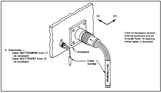
|
Note: Disconnect cable 30V77W28P66 from J1 on keyboard; Disconnect
cable 30V77W2P67 from J2 on keyboard |
Reference: 218, p. K-6;
NASA-STD-3000 34
Figure
11.14.4-2 Spare or Test Cable Identification Methods
Reference: 249, p. H-43;
NASA-STD-3000 35
Return to Volume I Home


.gif)
.gif)
.gif)
.gif)
.gif)


.gif)
.gif)
.gif)
.gif)
.gif)


.gif)
.gif)
.gif)


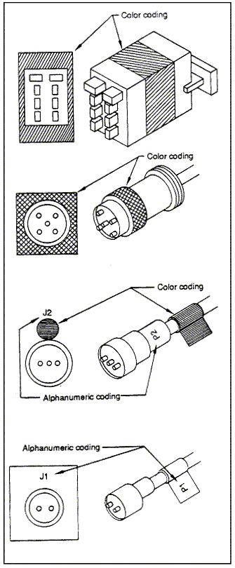

.gif)
.gif)


